Skip to content

IW5EDI Simone – Ham-Radio

Amateur Radio made in Italy

Menu
  • About me
    • QSL info
    • Log Book OnLine
    • What I Hear
    • Live Stream
    • Perchè (Why) in English ?
    • Contact me
    • Privacy info
  • Software
    • Ham Radio Deluxe 5.2
    • IP-Sound
    • OscillometerXZ
    • YO Yagi Optimizer
    • HamAlyzer 2.8
    • ERP Calculator
    • 59+ software
    • Magnetic Loop Calculator
    • MeterMate
    • UDY 2 Voice Keyer
  • Ham Radio
    • Beginners Guide to Ham Radio
    • Direct QSLing from Italy
    • Foreign Ham Operations in Italy
    • Tourist Ham Radio in Italy
    • Frequency List
    • Metric Conversion Table
    • Sound Card Interfacing for RTTY, PSK31, and SSTV
  • Technical Articles
    • Microphone Connections
    • A low cost 600 watt ultra-linear amplifier
    • VE7AVV – YAESU FL-2100Z Amplifier Repairs
    • Mic Wiring – Ham Radio
    • Homebrewing a balun
    • Grounding Concepts
    • HF Scanning frequencies
    • Wi-FI: Measuring network throughput
    • Determining RFI problems in mobile
    • Hidden and stealth antennas
  • Antennas
    • 144 / 430 Dual Band J-pole antenna
    • 10 Meter 4 Element Quad Antenna
    • 144 Mhz Magnetic Loop Antenna
    • A “loopy” Loop Loaded Vertical
    • W5GI Mystery Antenna
    • A Multiband Dipole
    • Build a W3DZZ Antenna
    • A portable 2-element VHF yagi
    • Assembling GAP Titan DX Antenna
    • The Galaxy Dipole
    • Pfeiffer Maltese Quad Antenna System
    • Magic Anti-Jamming antenna
    • D3+ High Performance Antennas
    • EH Antenna for 40 and 20 meters
    • Homebrew G5RV
    • 40 meter mini Moxon Antenna
    • EH Antenna for 10 meter
    • Quad and ModQuad Antenna
    • Inverted U antenna for 160 meters
    • 6 Band HF Windom antenna
    • The Bazooka Antenna
    • Antennas for HF mobile operation
    • Inverted L Antenna for Low Bands
    • Your first dipole
    • Remote control Antenna Switch
    • The gin pole
    • Hexbeam antenna setup
    • W4TI Rotor Installation
Menu

How antenna traps work

Posted on April 29, 2020April 29, 2020 by Simone

Article by VE3GK

I was assembling a HY/GAIN, TH6DXX, a 10 – 15 and 20 meter beam the other day and thought there might  be some interest in the function of the traps. I have also included some practical information on how
to build traps for a multi-band, 10-15-20 meter antenna.

RESONATE PARALLEL NETWORKS REVIEWED:

When a certain amount of capacitance is connected in parallel with a certain amount of  inductance it  results in a very high resistance at a certain frequency. In other words this combination of inductance and capacitance results in a special high resistance resistor designed to work at a narrow band of frequencies.  Other frequencies above and below this frequency exhibit the opposite condition, a very low resistance.

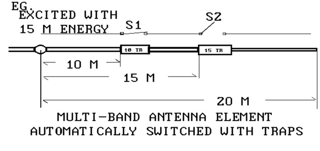
TRI-BAND ANTENNA ELEMENT TRAP EXAMPLE: EXAMPLE:

When a Tri-band 10, 15 and 20 meter beam is excited with 21 MHZ energy only the length of element to the 21 MHZ trap is used.
The trap is situated 1/4 wave length from the boom of a yagi and is similar to that of an open switch.
The same electric circuit is present on 10 meters. Conversely, the 14 MHZ signal perceives the 21 and 28 MHZ traps as a closed switches at 14 MHZ. The 20 meter signal and uses the whole length of the element.

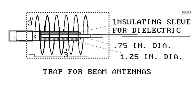
TYPICAL TRAP FOR 20–15–10–METER BEAM

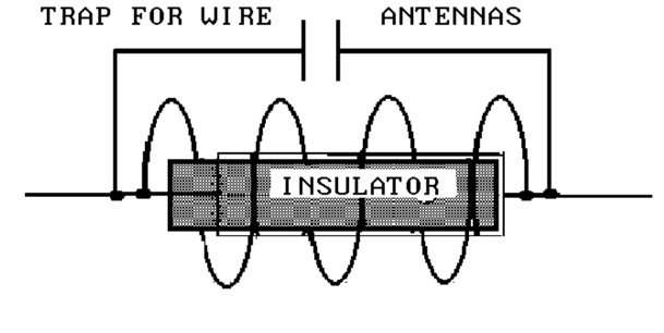
Please refer to the following drawings for the practical application of the parallel tuned traps that are used in multi band beams and wire dipoles. The capacitor is made by inserting one aluminum tube inside another with an insulating sleeve in between serving as the dielectric.

The capacitance should be around 25 pf. for the 15 and 10 meter bands when the tubes over lap about 5 inches.
The dimensions of the coil determine the frequency of operation. The coil is air wound from one tube to the other.
The diameter and length of the coil should be about 3 inches. Allow 7 turns for 15 meters and 5 turns for 10 meters.
Approximately number 8 aluminum wire should be used.

The final tuning should be done on both networks with a grid dip meter. Adjustments should made to the coil and capacitor to resonate the network at the lower edge of the designated band.

TYPICAL TRAP FOR 20–15–10–METER WIRE DIPOLE

The same values of inductance and capacitance apply. It is important that the voltage rating of the capacitor be in the 2 to 3 KV range. Several lower voltage capacitors could be assembled in series to make up the required voltage rating. The higher the power the higher the KV rating should be. 
Remember when identical capacitors are installed in series you have to divide the value of one of them by the total number of capacitors in the string to get the total value of capacitance.

1 thought on “How antenna traps work”

  1. Mike says:
    May 20, 2021 at 5:00 pm

    Hi,

    IHow do you in practise measure the trap frequency response in a fritzel type trap as seen on a 1-15-20m trap used on a 3 element beam or rotating dipole.
    Do you need to get the grid dip oscillator coil inside the trap?
    If you take them apart, you no longer have a tuned circuit.

    Mike

Leave a Reply

Your email address will not be published. Required fields are marked *

This site uses Akismet to reduce spam. Learn how your comment data is processed.

IW5EDI Simone

  • Licensed Amateur Radio operator in 1996 as IW5EDI, active member of ARI Firenze and ARRL
  • Class 1970, married with two childrens, love experimenting and antenna home-brewing. IT System Engineer, recently started having fun with morse code and Raspberry Pi


IW5EDI Simone


This Blog is mainly dedicated to Amateur Radio (Ham radio) and contains external articles and personal esperiences.

What is Amateur Radio ?
More Ham Radio Links


Blogroll

  • ARI Italian Amateur Radio Society 0
  • ARI Firenze ARI – Sezione di Firenze 0
  • ARRL Amateur Radio Relay League 0
  • DX Zone Ham Radio Internet Guide 0
  • DXSummit 0
  • DXWatch 0
  • eHam 0
  • Ham Radio Daily Ham Radio News 0
  • IW5EDI on QRZ.com My page on QRZ.com 0
  • Long Delayed Echoes 0

My Content

  • Antenna Projects 0
  • RadioAnnunci.it Mercatino Radioamatoriale 0

Categories

  • Articles (131)
    • Antenna Theory (13)
    • DXing (2)
    • How to (10)
    • shortwave (7)
  • Company and Products (1)
  • DXing (13)
    • QSLing (4)
  • Equipment (97)
    • Antenna (65)
    • Software Defined Radio (6)
  • Featured (28)
  • Ham Radio Events (25)
  • Ham Radio News (1)
  • Ham Radio Software (26)
  • HamRadio (94)
    • Ham Radio 2.0 (16)
    • How to (6)
    • Radio Scanning (6)
  • Homebrew (142)
    • HF Antennas (78)
    • Raspberry Pi (1)
    • UHF Antenna (16)
    • VHF Antennas (38)
  • Photos (4)
  • Short News (4)
  • Video (4)

Comments

  • Charles Mintoff on Ham Radio 2012
  • Roger Sparks, W7WKB on Petlowany Antennas by K6NO
  • Frank Barnes on Ameritron AL-80A restoration project
  • ken m3zkb on W5GI Mystery Antenna
  • Bobby on 5/8 Vertical Ground Plane antenna for 10 meters

RSS The DXZone.com

  • Top Amateur Radio Websites - Issue 2603
  • FT2: New Ultra-Fast Digital Mode Tested on HF
  • Top Amateur Radio Websites - Issue 2602
  • The G3LZR Tribander : The charm of the Impossible Antenna
  • Top Amateur Radio Websites - Issue 2601
  • Amateur Radio Clubs
  • Shrunken Quad
  • DIY Magnetic Loop Antenna Tutorial with Remote Tuning System
  • HF Beacon Tracker: Real-Time 3D Propagation Visualization
  • WSJT-X FT2 fork Decodium

Ham Radio Blog – IW5EDI Simone JN53OR

© 2026 IW5EDI Simone – Ham-Radio | Powered by Superbs Personal Blog theme