Double Bazooka Coaxial Dipole Antenna Info
There is a lot of controversy surrounding the Double Bazooka Coaxial Dipole. Its bandwidth claims have sometimes been exaggerated.
On this page I give details of how to build two different versions of the Double Bazooka Antenna. One antenna uses all coax the other uses coax and twin lead for the antenna.
A DOUBLE BAZOOKA antenna is an extremely broad banded Half Wave Antenna which can operate efficiently across an entire Ham band with little change to the SWR. The BAZOOKA antenna design was developed by the staff of M.I.T. in the early 1940’s for use by the U.S. Government as a radar antenna. It was modified for amateur radio use in the 1950’s.
This unique design eliminates the need for antenna matching baluns and can be fed directly with 50 Ohm coax.
The DOUBLE BAZOOKA is 98% efficient and typically provides S.W.R. readings of less than 2:1 over the entire amateur band.
Since this antenna has no exposed metal wire static charges can not build up thus reducing noise by 6dB over antennas constructed of exposed wire.
The DOUBLE BAZOOKA antenna will handle full legal limit power with no effect to performance.
The DOUBLE BAZOOKA is recommended to be mounted in an inverted “V” configuration for optimum results. However the DOUBLE BAZOOKA can be configured horizontally with equally good results.
The 80 Meter DOUBLE BAZOOKA antenna will operate on 80 through 10 meters with the aid of an antenna tuner.
The following chart gives overall antenna lengths and recommended height placement above ground for a single DOUBLE BAZOOKA.
Band     ANTENNA      Center height     End Height
         Lenght        above Ground     above ground

17  M    25.4 feet       25 - 35 feet     7 - 10 feet
20  M    32.4 feet       25 - 35 feet     7 - 10 feet
40  M    64.0 feet       25 - 35 feet     10 - 15 feet
80  M   121.0 feet       40 - 60 feet     15 - 20 feet
160 M   248.0 feet       60 - 90 feet     15 - 20 feet
If erected as a Dipole this antenna has horizontal polarization.
This antenna can also be installed in an inverted V fashion “Center elevated, with 90 – 120 degrees between the legs” Then it will have vertical polarization and will usually out perform a dipole type antenna at distances of over 500 miles due to its lower angle of radiation.
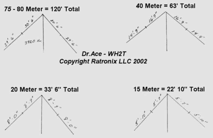
The coaxial dipole uses the same type of coax for the feed line as the legs are made of or it will not work properly. I’ll use the 75-80 Meter antenna as an example.
To build one of these antennas resonant at 3.920 Mhz.
Measure out a 120 feet length of coax and cut,this will be the antenna. At the center of this cut off 1″ of cover all the way around and remove. Now cut the shield all the way around and separate. Do not cut the dielectric. This is the point at which you will support the antenna so make a hanger from rope or other material.
Take your feed line coax and cut back cover at one end so as to be able to separate the center conductor and shield. Attach the feedline center conductor to one side and the shield to the other side of the antenna coax shield at the center of the 120 foot long piece.
Next, measure down each leg 30′ 6″ from the center and cut a slot in the cover and shield, so as to be able to get to center conductor.
At this point solder the center conductor to the shield on both legs. Now seal the center point and each leg where you soldered, with nonconductive silicon, so as to make weather tight. At the end of each leg strip the shield and center off and solder shield to the center conductor so it will not separate and seal.
The center conductor from leg to leg acts as a balun, thus making this antenna able to operate with a very low SWR across the whole band. 40 Meter Addendum I have NOT personally built these antennas.
I was informed by KB5HOV that using my design he made two 80 mtr and two 40 mtr double bazookas “using RG-8 for the entire antennas” when he constructed the 40 Mtr bazookas he had to add 18 inches to each end section to get them resonant in the phone portion of the band.
This was true on both 40M antennas but after the extra 18″ length was added they were 1:1 VSWR at 7.215 Mhz and 1.1:1 VSWR at 7.295 Mhz.
Double Bazooka Dipole Antenna Version #2
This adaptation used in amateur radio only uses coax for the broadbanding portion of the antenna, while the remaining portion of the elements are constructed of twinlead or ladder line (see attached sketch below). Ladder line is preferable for its inherent strength.
This is a single band antenna. It will not radiate harmonics of your operating frequency. In addition, there is very little feedline radiation, which is great for those who have problems with TVI. Its broadband characteristic makes it ideal for 80 meters and 10 meters.
The Bazooka antenna consists of a half- wavelength of coaxial line with the outer conductor opened at the center and the feedline connected to the open ends. The outside of the coax and the ladder line operate as a half-wave dipole. The inside of the coax elements, which do not radiate, are quarter-wave shorted stubs which present a high resistive impedance to the feed point at resonance. Off resonance, the stub reactances change in such a way as to cancel the antenna reactance, thus increasing the bandwidth of the antenna.
At the very center of the coax carefully cut away about one inch of the outer vinyl jacket.
Then cut the exposed shield all the way around at the center of the exposed area. Be careful that you do not cut the dielectric material or the center conductor in the process. Twist the two pieces of exposed shield into small pig-tails. These are the feed-point terminals for the antenna. The center conductor of the feedline is soldered to one and the shield of the feedline to the other. Now solder the center conductor and shield together at each end of the coax antenna element. Solder the two ladder line wires to the end of the antenna element. At the other end of the ladder line, solder the two wires together.
The two conductors at each end of each piece of ladder line should connect to each other.
“Don’t connect one end to the other end of the ladder line”
“Think of it as connecting the two conductors in parallel”
Use a square piece of plastic at the antenna center, drilling a small hole on each side of the coax, wrapping a small wire around the coax and through the holes and twisting the wire together on the other side. A small amount of quick setting epoxy secures the coax to the plastic support and prevents the wire from untwisting.
A coating of silicone rubber or epoxy seals and protects the feed-point from the weather. Do the same where the ladder line is soldered to the shorted end of the coax.
Short the center to shield at each end of the coax. Short the twin lead at each end and solder the coax/shield junction to the coax. Use 50 Ohm Coax feedline at least 66 feet long.
_ _____| |_____ _
[]- [_______________________]- [_]
Twin-Lead * * * * * * * * * * * COAX * * * * * * * * * * * Twin Lead
<---------L=325/Freq--------->
coax length
<-----------------------L=460/Freq------------------------->
Total Overall Length
Total Overall length minus Coax length = Total Twin lead length.
Example: 3.888 Mhz.
Total length 118.3 feet
Coax length 83.6 feet
Twin lead length 34' 8 1/2'' feet total or 17' 4 1/4'' on each end of the antenna.
Addendum
Added December 2004
I made this page quite some time ago.
This is ALL the info I now have on Double Bazookas.
I have NO other formulas, info, etc.
Please DO NOT eMail me with questions about Double Bazooka antennas.
All Copyrights to W2HT article originally available at http://www.bloomington.in.us/~wh2t/bazooka.html
I built the 40m one and the results are fantastic, on a long wire was 5/6 now 5/ 9 receiving great and hardly any noise before was ave 5 to 7 been a m3 for 16 yrs check my qrz page regards men m3zkb