Mobile Antennas
This is an area of hot competition among antenna manufactures. I am not going to cover how to mount your mobile antenna (Radio Shack sells everything you need to mount antennas), but the basic mobile antenna designs that most mobile antennas manufactures are using today. If you have just started reading my page and are new to antennas, you are going to be confused. You cannot just jump right into putting together an antenna without learning a few things about them first. You have to read “Antennas Basics”, “Coax Basics” and the “Verticals” sections first before you tackle this section. First we need to introduce a new term that we will be using to rate mobile antennas (gain really isn’t a good thing to use, since mobile antennas generally have no gain), “antenna efficiency”. This is how well the antenna converts your power (watts) to signal instead of wasting it as heat. An efficient antenna puts most of the power out as signal, so the range of 95-99% is a perfectly efficient radiator (all antennas waste some power, none are 100% efficient). Most base station antennas are 95-99% efficient. Say you are using 100 watts, and your antenna converts 95 watts to signal and turns the remaining 5 watts into heat, this is a 95% efficient antenna.
The most efficient mobile antenna is the 102″ whip. If you desire the best performance, the 102″ (quarter wave) whip is the only way to go. If you look back to the “Verticals” section and look at the ground plane (figure 1 in “Verticals” section) you can see the main vertical element is basically a 102″ whip. The center wire connects to this part. It must be insulated from the vehicle body. This is usually accomplished by a plastic washer. Now, the vehicle body acts as the ground plane, or like the radials on the ground plane antenna! The feedpoint impedance of the 102″ whip when mounted on most vehicles is 40 Ohms, so the lowest SWR you can get is 1:3:1. When you assemble this antennas system, if the SWR is above 3:1 on all the 40 channels, then you have a bad connection somewhere. If your coax is ok (see “Coax Basics” section) then you probably have a short or open circuit on your connection to the whip. Check the connections with an Ohm meter, center pin of radio side of coax should have an electrical connection to the actual whip and not the body of the vechicle, and the collar of the radio side of the coax should have an electrical connection to the body of the vehicle and not the whip itself. Make sure your assembly is right. If everything is assembled right, you should see an SWR 2:1 and lower (down to about 1:2:1) over the 40 channels. Really, your whip should not need adjustment, so before you think about “pruning” it, you better check to make sure things are working right. Do not let the 2:1 SWR fool you, getting it down to 1:2:1 will not get you much more (if any) performance! The only exception to pruning your whip is if you intend on talking above channel 40. If you use, lets say 27.555MHz, then you will need to trim a few inches off the tip of the antenna. Start by trimming a 1/4 of an inch off at a time and rechecking until your SWR is where you want it.If you need to lengthen the antenna, you can do so by added a spring or quick-disconnect fitting which will add around 2 – 4″ to the overall height. This should get you well below channel 1 with a low SWR.
Most of us do not have room to use a 102″ whip on our vehicle. Plenty of manufactures make a shortened antenna for our use. How do they do that? Simple, somewhere on the antenna (the base, center, top or entire antenna) they wind a coil to compensate for the length that they are shortening the antenna from 102″. So if your mobile antenna is 54 inches, the manufacture has made a coil to compensate for the 48″ inches they are short from 102″ (102 – 54 = 48). When a coil is added to an antenna it does three things. One, it cuts down on the antenna’s efficiency. Second, it cuts down on the bandwidth. Third it cuts down the antennas impedance (it lowers it even more than 40 Ohms). The shorter the antenna is made, the more these three factors are reduced.
Extremely short antennas are to be avoided at all costs. There are differences in efficiency between the different methods of “loading” (placing a coil on the antenna to compensate for shortening it) a mobile antenna. The four types of loading are base, center, top and continuous loading. Figure 1 shows the four types of loading.

Their performance can be summarized like this. If these antennas are all the same length (say 54 inches) the least efficient antenna is the base loaded whip. Its advantage is that you can make a heavy coil that will have a higher power handling capability than a center loaded or top loaded mobile antenna. A thicker coil handles more wattage, but you could not have a heavy coil in the middle of the antenna or top because the antenna would not be able to support it (it would be too “top heavy”). But still, it is the least efficient of all the shortened antenna types. For improved antenna efficiency, you could use the center or top loaded antenna. The center and top loaded antennas have about the same efficiency, so there really is no difference. You will mainly find only center loaded antenna however. Top loaded antennas are rare because they are more difficult to make strong enough to support the wind load. The most efficient of the shorten mobile antennas is the continuously loaded mobile antenna. It is usually a fiberglass rod wrapped up its whole length with a copper wire or flat ribbon. Use it when you must use a shortened antennas and want maximum performance. Use the longest possible for your vehicle. Its only disadvantage is it usually cannot handle high power (like over 500 watts) because it has to wrapped with a thin wire so its flexible and light.
A glance at the different mobile antennas for sale results in extreme buying confusion. First and foremost, the mounting location is the most important aspect to performance. You must get as much of the antenna over the top of the vehicle as you can. Roof mounting is most desirable, followed by trunk deck / hood mounting then lastly bumper mounting.
Most fiberglass whip makers are claiming their antennas are 1/2 wave, 3/8 wave, 5/8 wave and 3/4 wave antennas. That sounds very impressive. But is it electrically true? Yes, the makers of these antenna wind the respective length of wire onto the fiberglass antenna but does the radiation pattern benefit from the extra wire length as claimed? In a nutshell, no. The extra length of wire (beyond 102″ inches) is coiled so closely together to be able to actually fit on a skinny fiberglass rod that it electrically ends up performing the same as the 1/4 wave antenna. There are some exagerated claims of performance from some companies.
Luckily, the performance difference between different makers is so minimal it almost better to pick antennas based on the antenna you like the looks of most!
Radiation Pattern of Mobile Antennas
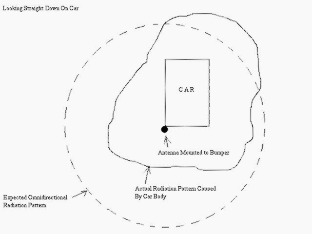
Most people think that antennas mounted on vehicles are omnidirectional. This is mostly true, but the radiation pattern is influenced greatly by the body of the vehicle. Remember we stated that the body acts as the “radials” for the antenna? Well, we know that the body does not extend around the base on the antenna equally. Figure 2 shows how the radiation pattern of a whip is influenced by the body of the vehicle. As you can see, the shape of the pattern depends on where you mount the antenna. The pattern is “pulled” to areas where there is the most vehicle body. The pattern is the worst in directions where there is no metal body for a radial.
Co-Phasing Your Mobile Antennas (“Twin Truckers”)
Co-Phasing antennas simply means taking two identical antennas, mounting them on the vehicle and feeding them in-phase. One of the biggest misconception of radio operators is what kind of effect this has on the radiation pattern. Most people think that after you Co-Phase two mobile antennas, your signal will be strongest in line with the vehicle body (meaning the signal is strongest down the road straight in front of you and straight behind you also. This is the theoretical effect that you would get from co-phasing two omnidirectional antennas. However, to realize this effect you need to satisfy a couple of requirements. For one, a good earth ground with long (over a wavelength or so) radial wires is required. Secondly, at CB frequencies the closest you would be able to place these antennas are about 18 feet apart. Since it is impossible to satisfy these requirements, the effect of co-phasing is seriously diminished. Unfortunately, even the “Radio Shack Antenna Book” states that co-phasing two mobile antennas will produce a two directional signal.
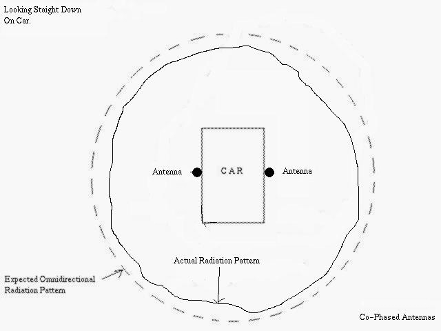
So then, is there any advantage to co-phasing two mobile antennas? Why yes, there is. Before we noted that the radiation pattern of a single antenna is “pulled” where there is the most metal vehicle body. You can see the pattern is not perfectly omnidirectional like we would expect it be. As we travel down the road, you will notice signal fade (“flutter” or “waver”) from this uneven radiation pattern. Co-phasing two antennas will even out the pattern irregularities. Instead of making the pattern more two directional, it will make it more omnidirectional. Do not expect more “gain” from two antennas. Figure 3 shows how co-phased antennas clean up the radiation pattern. Read the section “Co-Phasing” for instructions on how to make a harness to feed your co-phased antennas. It best to get them as far apart as possible. The best way would be to mount one on the front bumper in the center and one on the back bumper in the center also. Most people think this looks silly (me included!) and mount one on each side of the vehicle.
Article by Scott 2rp789 originally available at http://signalengineering.com/ultimate/mobile_antennas.html