
Directional Antennas
An antenna is known as “directional” if its pattern strongly favors a certain direction. A directional works by concentrating the signal in one direction at the expense of other directions. Also known as the “Beam” antenna.
Read the section on Yagi antennas if you are not familiar with directional (“beam”) antennas and how they work. Since the Cubical Quad works off the same principles, you must first understand the Yagi antenna.
The Cubical Quad
The next type of beam is the Cubical Quad, my favorite. This is the type of beam that I use. There really is not any new principles involved here, the quad works on the same principles as the Yagi. However, instead of using the dipole antenna for the driver, director and reflector elements, we are going to use the quad loop antenna. The quad loop was invented by an amateur radio operator by the name of Clarence Moore. He was working for a broadcast station in Quito, Ecuador.
It is called a quad loop because most people configure it as a square (quad = 4, 4 sides to a square). The quad loop measures exactly 1/4 of a wavelength on each side. As you can see, this antenna actually is a Full (1) wavelength antenna as compared to the 1/2 Wavelength driven element of the Yagi. The loop is usually made from a 36 foot piece of copper wire. The Quad loop alone has 2 db of gain over the dipole antenna. So, using this as the driver element our antenna already has at least 2 more db gain over a yagi antenna with the same number of elements.

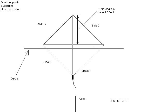
Take a look at the quad loop in figure 1. As you can see, each side of the loop is 1/4 wavelength. The total distance around the loop then equals 1 full wavelength or 36 feet. Figure 2 show the quad loop with a common supporting structure. The arms that hold the wire (usually #12 or #14 copper wire) are made from fiberglass, wood or bamboo. Really, anything that is an insulator can be used. Keep in mind, it must be strong. Wire is light, but when the wind starts hitting it or ice builds up on the wire, weak supports will break.
Another point I would like to point out about the quad loop is what it is really made up of. In figure 2 side A and side B can be thought of together as a dipole antenna. You can see if you remove side C and side D you would just have a dipole who’s legs (each 1/4 arm) slant up at an angle. Then you can see if we add sides C and D, and join them all together, we really have just hooked two dipoles together! This is equivalent to co-phasing two dipoles. Read the “Co-Phasing” section for more information about what we mean. This arrangement doesn’t quite give us the 3db we would expect, but it does up our gain over 1 dipole by 1.8db.

Figure 3 shows a drawing to scale that compares the sizes of the quad loop element and the dipole. This is just to give you an idea of size requirements. Figure 4 compares the radiation pattern of the dipole antenna to the quad. When you are using the dipole, you can just feed the antenna in the same place (the middle) and rotate the antenna to achieve a different polarization. But since the quad loop is a loop, rotating it would not do you much good. To obtain a certain polarization with a quad it matters where you attach the coax. Figure 5 shows the feedpoints to obtain a certain polarization. Each of these feedpoints have the same impedance.


One of the biggest advantages to using the quad loop that it is impervious to rain/sleet/snow/sand static noise. Have you ever had rain static pound your receiver when a rain storm was rolling in? Things such as sand and rain carry an electrical charge that cause a lot of noise on verticals and yagi beams. Surprisingly, the closed loop of the quad does not respond (pick up) to this type of noise. As a matter of fact, in Operation Desert Storm, Yagi beams where unusable because of the sand storms that cause huge static noise problems! The U.S.troops had to use quad antennas to communicate during sand storms.
Lets take a look at some 4 element cubical quads. Figure 6 shows a 4 element cubical quad fed for horizontal polarization. The elements create a beam pattern the same way a yagi does (see the “yagi” section). The parasitic elements are closed loops, meaning they are not electrically broke at any point around. All the wire loops must be insulated from the boom. Fiberglass is usually used on durable quads. The reflector element is typically 10 % longer (the distance around the wire loop) than the driven element and the director is typically 10 % shorted than the driven element.

Another huge advantage of the the quad parasitic element is the fact that it is not polarization sensitive. By this we mean, quad parasitic elements (reflector and director(s)) respond to all types of signal polarization equally well. Compared to the yagi elements, where the element is either in the vertical plane (straight up and down) or the horizontal plane (side to side) . These yagi elements only respond to signals that have the same polarization as their self. All other signals (that do not match their polarization) are reduced by 20db (I mentioned this under the “Antenna Basics” section)!
The quads parasitic elements are a continuous (closed) wire loop, that respond equally well to all polarization’s. This means they direct or reflect horizontally polarized waves, vertically polarized waves and everything in between (they direct/reflect all signals equally well regardless of its polarization). Keep in mind the driven element is broken where the feedline connects, which means the driven elements IS polarization aware.
What this mean is, during DX contacts when signals arrive at your antenna with its polarization changing constantly (this is one reason signals fade and pop back up suddenly), on the quad this effect is reduced because quad parasitic elements still pick up these changing (flip-flopping polarization) signals. Notice I said parasitic elements, the driven element still reduces signal strength by 20db (if the signal doesn’t match its polarization)..but the signal is stronger than it would be on the yagi because the yagi parasitic elements would have also reduced the signal by 20db before re-radiating it (for the driven element to then pick up).
If you are confused about polarization “flip-flopping” or changing during DX contacts, you need to do some further reading, check out my section of recommended books. You must keep in mind signals bounce off of objects (water towers, radio tower, water, the ionosphere) and their polarization gets rotated somewhere in between horizontal and vertical most of the time. I can not cover every aspect of how signals travel (called “propagation”)…I would be writing for ever! Under the “Angle of Radiation” section, you get get an idea of how “skip” (DX) signals travel.
Since our antennas are generally set up to receive only one polarization at a time (usually horizontal or vertical), polarization changes due to reflections can cause signal fade (signal strength waving up and down). This fading is reduced on quad elements! Enough said.
Lets look at the 4 element cubical quad fed for vertical polarization. See figure 7. Nothing new to really say, but you can see where the coax attaches for vertical polarization.

With these great features comes some disadvantages! First off, remember in antenna basics when I talked about bandwidth and said that it is mainly dependent on the antennas elements outside diameter? Well, as you can see from the pictures, we usually make quads from #12 gauge wire. This is small compared to the tubing you would normally use for a yagi, and as a result the bandwidth of the quad is narrower than the yagi. Generally you can just cover the CB band with a 4 element quad with a 2:1 SWR. If you are the type of operator that is all over the place (even outside the CB band)…this antenna will put a limit on your frequency range! More elements narrows bandwidth on any antenna type (quad or yagi), so a 2 element quad has better bandwidth than the 4 element quad.
Secondly, We are familiar that Yagi’s can be cross mounted (see figure 8 under the “Yagi” section), one for vertical and one for horizontal on the same boom. Now think, two quad wires, its not so easy, check out figure 8 to see what I am talking about. It is possible to mount to wires side by side, but this is slightly more complicated. A company by the name of Signal Engineering is making quad antennas that deal with this problem effectively.

Maco has a few antennas that they call “quads”. The V-Quad is a true quad. It actually uses a full wavelength loop for the driven element. If you shape the quads elements like a triangle (three sides instead of four) it is called a “Delta Loop”. It uses the exact same principles as the quad and has similar performance. The other antennas they call a quad is the “Y-Quad”…this is actually a hybrid – see the “Hybrid” section. To sum up the Y-Quad, it really is a Yagi antenna (because its driven element is a dipole, not a full wavelength quad loop…I am guessing the “Y” stands for Yagi). JoGunn’s V-Series are also the delta loop variety (they falsely state that they are “circular polarized”). New tests show that loop in a quad (4 sides) configuration yields slightly more gain than the delta configuration. The best configuration would be a loop arranged in a a perfect circle (instead of a 4 sided quad, or three sided delta), but that arrangement would be difficult and expensive, so the four sided quad is the closest practical way to form a loop at 27 MHz.
Here are some gain figures for some Cubical quads:
|
Number of Elements
|
Gain (Over Dipole) |
Front-to-Back Ratio (F/B Ratio) |
Comment |
|---|---|---|---|
| 2 |
5 dB
|
12 dB
|
Reflector element only
|
| 2 |
7 dB
|
Zero
|
Director element only
|
| 3 |
10 dB
|
15 dB
|
|
| 4 |
12 dB
|
25 dB
|
|
| 5 |
12.1 dB
|
30 dB
|
|
| 6 |
12.2 dB
|
30 dB
|
|
| 7 |
12.3 dB
|
32 dB
|
|
| 8 |
12.4 dB
|
32 dB
|
Note: This table is typical performance of Quad’s with the stated number of elements. Typically, the gain will be within 2 dB of the indicated gain. However, Front-to-back ratio can vary greatly (as much as 25 dB) from the indicated F/B. F/B is much more sensitive to adjustments to the element length and spacing.
As you can see, the Cubical Quad antenna has the same gain as a yagi with one more element..because the driven element of the quad has more gain than the Yagi’s driven element (2db more). Figure 8 shows a commercial 4 element quad available in the Netherlands.


I give construction details of my 4 element cubical quad under the “Antenna Building” section. Check it out if you want to build a killer DX antenna!
Article by Scott 2RP789 originally available at http://signalengineering.com/ultimate/cubical_quad.html