While browsing through my new copy of Simple and Fun Antennas for Hams one day in the Spring of 2003, I discovered an interesting looking design, with an interesting name – the Hentenna. The versions described were made of wire and cut for 6 meters, although it was suggested that the design could be used on other bands as well. l was looking for a 2 meter antenna to use for a second rig, and I thought I could adapt this design to 2 meters easily.
Some Hentenna Background
The Hentenna is a loop style antenna developed by Mr. Tadashi Okubo JH1FCZ, Mr. Someya, JE1DEU and others in Japan in the 70’s. It was first described in the US in a Feb 1982 QST article by Koji Sugihara, JJ1UMS and Shirow Kinashita, JF6DEA/KE1EO wrote about it in the ARRL Antenna Compendium Vol. 5. The gain is approx. equal to a 3 element tribander, JH1FCZ reported 5.1 dBd in 1972, yet it is small compared to a beam. 1
It looked like the type of antenna I wanted to try on 2 meters, small and with some gain. However it also looked like it was a little complex to build for what I had in mind.
DESIGN GOALS
I wanted it to be very easy to build, broad banded, and inexpensive, all good antenna attributes. It looked like a good candidate for a “plumbers delight” copper pipe project. A major consideration was to build it so it required no tuning of the feed point. So I scaled the dimensions for 2 meters and began to experiment.
Several prototypes were constructed of ½” copper water pipe and fittings purchased at the local hardware store, empirically arriving at the final dimensions below.
BUILDING IT
I recommend building the ½” copper pipe 2 meter Hentenna to these dimensions:
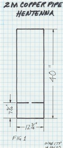
Overall length = 40 inches Overall width = 12 ¾” Feed point = 7 3/16” to center line of T connector
You’ll need one 10′ piece of ½” copper pipe, four right angle elbows, two tee’s, and two end caps from the hardware store, total cost about $12. With the dimensions below you can just jam it all together, apply the heat and solder and it will work just fine. Or you can be a little fussier and adjust the dimensions perfectly before soldering. I used a tubing type cutter; it’s much easier and more precise than a hacksaw. Use a propane torch and apply the heat to the fittings so the solder wicks into the joint, sometimes referred to as “sweat soldering”.
Cut the pipe as follows:
2 pieces 31 13/16” for the long side pieces above the Tee’s 2 pieces 6 1/16” for the short side pieces below the Tee’s 2 pieces 11 1/2” for the two end pieces 2 pieces 5″ for the feed points.
Use lead/tin rosin core solder, and shine up the ends of the pipe and the insides of the fittings before soldering. I just laid it out on the garage floor to keep it flat and applied the heat. Be sure to wear safety goggles since concrete may “pop off” little pieces when overheated.
The caps go on the end of the feed tubes and the distance between them will be around 3/4″. Solder the coax braid to one cap and the inner conductor to the other; just tack them on, ugly style. There’s no tuning involved; the position of the tees takes care of it for you!
TO B OR NOT TO B (Balun that is)
A balun probably should be used to preserve the radiation pattern. But while experimenting with the prototypes, I discovered that any metallic objects inside, on or near the loop had major effects on the match. So I just stuck the coax on without a balun and it seems to work just fine, in a practical sense, at my QTH.
INSTALLING IT
Here are several things to consider when installing this antenna.
1. Use a non-conductor for the mast. I used 1 ¼” schedule 40 PVC pipe.
2. For the vertically polarized version, tape or cable tie the coax to the middle of the end piece nearest the feed point, NOT the mast. Let it hang over the end some then attach it to the mast below the antenna. Side mounting the antenna may be a better option.
3. Use non-conducting hardware to attach it to the mast. Steel or brass hardware has a really detrimental effect on the match. During the course of experimentation I’ve used nylon bolts, tape, cable ties, and wood dowels. Nylon boltsare by far the best mechanically and the easiest to install.
NOTE: The signal polarity is perpendicular to the axis of the feedline.
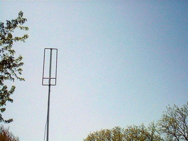
4. For a vertically polarized signal for repeater use, the 40″ dimension must be horizontal to the Earth. Typically this is the orientation for working FM mobile and repeaters. See the top picture at the right.
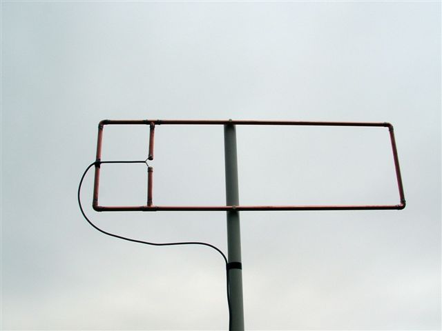
5. For a horizontally polarized signal for ssb or CW, the 40″ dimension must be vertical to the Earth. See the bottom picture at the right.
Article by WA0ITP originally available at http://www.wa0itp.com/hentenna.html