Original article by K7ZB

The simple 15′ vertical antenna shown mounted on the railing of our second floor deck has produced almost 200 countries worked around the world… VQ9’s in Chagos and 3B8’s on Mauritius in the Indian Ocean, TX0DX on Chesterfield Reef, VK0MM on Macquarie Island in the Antarctic region, BQ9P on Pratas Island off Taiwan, ZM7ZB on Chatham Island in the South Pacific along with FO0AAA on Clipperton, 9M0OO on Spratly Island in the South China Sea, JT1CO in Mongolia and on and on. What I hear, I can usually work with this little wonder and the small size and profile make it feasible for use in deed restricted neighborhoods.
A radio amateur friend and antenna designer came up with a simple design for a 10 meter vertical, which another friend and I modified to make work for the 14, 18, 21, 24 and 28 MHz ham bands. Its performance surpised us, and I’ll share it with you, in case you too are looking for a simple, inexpensive DX antenna that really performs well.
Main Antenna Concept
The basic concept is to put up a piece of aluminum tubing with a telescopic section held by a small hose clamp to adjust the height. By attaching the center conductor of a coax feedline to the tubing, and the shield of the coax to a couple of radials from the base of the tubing you can load the vertical across quite a broad range of frequencies.
Of course, with a vertical element of approximately 15′ this is a non-resonant antenna for the 10, 12, 15, 17 and 20 meter bands. I chose this length on purpose to allow the system to be tuned to resonance with an antenna runer.
Tuning
Since the SWR in an antenna system of this type will be relatively high, an antenna tuner unit will definitely be required. You may need an external ATU if the one in your transceiver can’t handle the impedance mismatches involved. Here at K7ZB, I drive my TS570 (which has a built-in ATU) thru the amplifier, which then drives a high power ATU to the antenna. I put the SWR/Power meter between the amplifier and ATU to ensure a good match for the amp, and in cases where I run barefoot without the amp, I can still use the ATU to assist the transceiver’s ATU in ensuring a good match.
In this way, everything is matched for maximum power output: from the transceiver to the amp, and amp to the antenna. And, even though the SWR’s are high at the feedline and the antenna, it doesn’t matter because the system is matched with the ATU.
Mounting Scheme
The picture below shows the details of the mounting scheme.
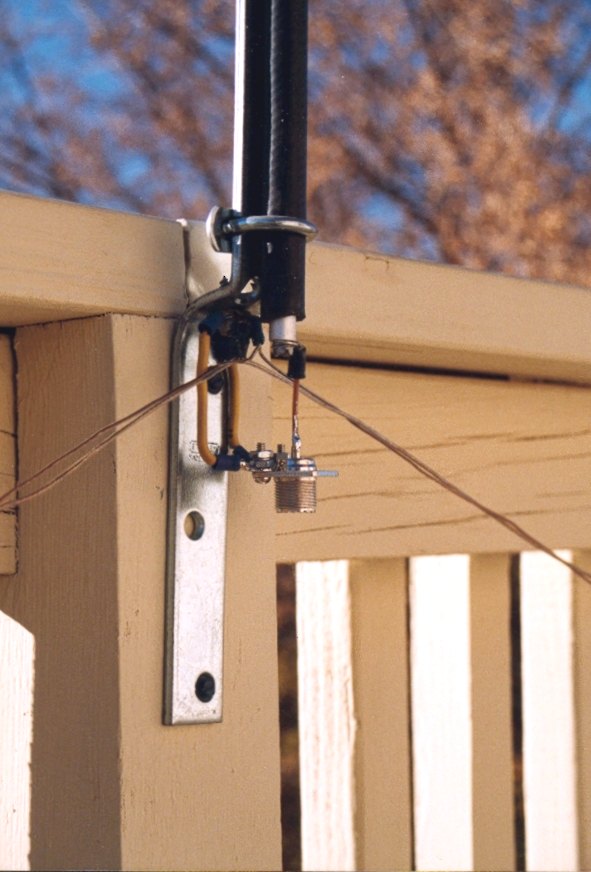 This picture shows the center conductor of the vertical connected to an SO-239 female coax connector. I used two pieces of insulated #14 AWG solid copper wire to provide a stiff means of supporting the connector to the metal bracket. Note that there is no true ‘ground’ connection to this antenna. The ground side of the connector simply connects to the hardware bracket, to which the two radials are connected. The bracket looks like a simple piece of offset metal used to mount a small flag pole or the like.
The two ~15′ radial wires are held to the bracket with a large sheet-metal screw, so the bracket is connected to the coax shield.
Electrical isolation from the center conductor of the coax connected to the vertical element is provided by an insulating rubber sleeve. This is a piece of neoprene fuel line chosen because the dimensions fit the aluminum rod inserted into the lower 14″ of the aluminum tubing. However, we found the electrical isolation properties of neoprene fuel line leave a little to be desired at the high SWR’s of this system. After driving this vertical with 500 watts at high SWR in the middle of one of the DX Contests, I punched through the insulation.
Obviously the original 10m antenna design was intended for lower power and lower SWR’s! This problem was solved by wrapping the neoprene sleeve with several layers of Teflon tape (the kind you buy for plumbing work at the hardware store). I also added a couple of layers of electrical tape (600V rating) for additional safety. These modifications are shown in the picture below with the vertical tubing removed – you simply add the tape over the sleeve. The vertical element is then secured to the bracket by a pair of hose clamps of suitable size.
A construction detail shown in the picture below is the solid aluminum rod that fits inside the lower 14″ of the main 8′ length of tubing. The solid rod is inserted at the bottom to ensure a good tight connection for the sleeve. This rod end can be drilled with a blind hole for a self-tapping sheet-metal screw to secure the solid copper wire from the center conductor from the SO-239. The tubing is secured to the rod with a hose clamp just above the top of the bracket.

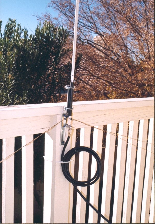
A tip for ensuring good clamping force with hose-clamps and hollow tubing is to slit the tubing about two inches up from the bottom on opposing sides with a hacksaw. This will allow the clamps to grip tightly enough to prevent slippage. Also, insert a solid piece of rod about 8″ long inside the smaller diameter telescoping tube at the top of the vertical to prevent that tube from collapsing. The upper telescoping tube is adjusted to about 15′ overall length to give proper loading across all bands.
The final photo below shows the completed vertical attached to the railing with the coax looped about 6 times to give some measure of RF choke action to keep RF from entering the shack on the braid. I secured the coax loops with plastic wire-ties to the railing support to stress relieve the connector. You can also see the tubing and small hose clamp just above the neoprene sleeve along with the two larger hose clamps gripping the sleeve and rod to the bracket.
It is quite easy to remove the vertical tubing element and stow it when you are not operating, as I now do, thus fulfilling the need for an unobtrusive HF antenna.
All in all, a cheap and effective radiator for the higher HF bands!
Article originally available at pages.zdnet.com/radio_k7zb/id8.html.
cud u pls send some rough drawings by mail pls, i am newly licensed fom india, call sign vu3mes
73s satyan
Clean workmanship! Good looking antenna….
I might suggest using a telescopic aluminum flagpole, as you can raise or lower it to work various bands.
73’s!
KD0DVS
Great article for those of us in Tampa on deed restricted lots.
In america and canada, due to ham radio being classified as an emergency service, you can skirt around all local and state/provincial antenna-height laws. good idea though.
Hi – I made Bob’s K7ZB 20m to 10m vertical and also his stealth 40m vertical (http://www.dxzone.com/cgi-bin/dir/jump2.cgi?ID=7544) – and both work really well.
Both are simple designs, straightforward to make and very cost effective too!
Plan to put another 20m to 10m one into service at my new home to work alonside my lower HF wires and rid my yard of commercially made HF antennas.
OM.
restricted by local and landlord laws and a smal yard i surfed the net looking for solutions to experiment. Some one’s are described as a wonder antenna but don’t believ it. All verticals use a ground or radials and are frequently monobanders. However, some known horizontal wire antennas can be erected to vertical and in mine opinion an antenna is like a coil and condensator You had to tune it. So one meets onpredictable problems ans solitions.
If you are restricted you can find on fleemarkets and hamevents material to experiment. and simon’s antenne is a fine example in recycling a CB antenna.
Simon said this kind of antenne had a high swr so start al you experiments with low power and a ATU the simpliest tuner saves your txr final a few euros spend to a (ferrit) coil and broadcast tuning condenser is cheaper then the power transistorrepai
the experimental antenna i build used a glasfiberfishing rod(old fashioned bamboo is o.k modern carbon is conductif)glued the pieces together an did not use the twiggy topsection. From foot to the top i wound copper wire approx 15 metres with a fingertip spation to start and 3mm 1/8 at the top
al windings glued with a drop epoxie.
First use eleved about 3 metres 10 feet by another piece of fishingrod tyraped together and uprected by 2mm steel guidewires some bands gives me a very high SWR difficult to tune away
Second attemp using a balun firts a cabelcurrent isolating a little better.but some bands not useable.
A second balun in the matching circuit first a 1 : 4 a lot better Then a 1 : 9 attemp again better.
The automatic ATU gives only a few clicks at changing bands and all bands are tuneable 50 – 1,8
for the experiment i dont use Amidon ferritcores but pieces of broken broadcast ferritantennas First tuning at 2 watts and when tuned i use for safety 60 watts but the sistem hold un
wanted accidentical full power 115 watts
the next eperiments are something with the radials shortened from 0,28 wavelength to 1,50 m 60″ and each band tuned by a coil like a shortened dipol
So simones antenne gives a lot of low cost experimenting and the results may suprise you
55 +73 Ruud
wooo ! i use this same type of antenna here in Cambodia i just run 63 ‘ of number 10 wire from my neighbor’s foof top/ down to my houses cement wall /with a glass wine bottle.. ! feed with rg59u coax; shield to a neer by cement wall ! 10watts am 1600 khz. ! lol ! 73s mr. Bill !
I’ve built this antenna from a 16foot aluminum pool skimmer handle.
Overall length is 16.75 feet with a small bit of very stiff copper wire on top..
Where the 2 sections join I have fastened it solid with sheet metal screw and placed a heavy copper ‘jumper’ wire over to the top section.
I made an ‘ugly balun’ attached at the feed point.
with 2 x 1/4wave radials for 10-15-20m.
It sits on top of a flat garage roof.
This antenna loads up with quite low swr on those 3 bands and the ATU in my FT-990 does the rest..with an outboard KW107 supermatch I can also run the bands in between. There is no RF in the shack unless a quite serious mismatch…the snow is starting so things seem to change a bit every day..
The sunspots are pretty good right now, and on all 5 bands I have been able to work anything I can hear all over the world 360degrees.
I’m actually quite surprised and very pleased at the performance…especially on 20m with a mere 1/4 wavelength or so..I have done no trimming or messing around with radial length.
Jim
VE7JM
Castlegar, BC, Canada
I am constructing this antenna from an old CB antenna which comes with 8 radials 1m 45 long and I would like to know if these would do or are the 2 x 15′ radials you specify essential.
Ian
M6PTA
UK
500Watts is a lot of power, no wonder it worked DX. Dx is more to do with Watts and peak of cycle than it being a good antenna.
Is there schematic available for this antenna? de VE4RI