Skip to content

IW5EDI Simone – Ham-Radio

Amateur Radio made in Italy

Menu
  • About me
    • QSL info
    • Log Book OnLine
    • What I Hear
    • Live Stream
    • Perchè (Why) in English ?
    • Contact me
    • Privacy info
  • Software
    • Ham Radio Deluxe 5.2
    • IP-Sound
    • OscillometerXZ
    • YO Yagi Optimizer
    • HamAlyzer 2.8
    • ERP Calculator
    • 59+ software
    • Magnetic Loop Calculator
    • MeterMate
    • UDY 2 Voice Keyer
  • Ham Radio
    • Beginners Guide to Ham Radio
    • Direct QSLing from Italy
    • Foreign Ham Operations in Italy
    • Tourist Ham Radio in Italy
    • Frequency List
    • Metric Conversion Table
    • Sound Card Interfacing for RTTY, PSK31, and SSTV
  • Technical Articles
    • Microphone Connections
    • A low cost 600 watt ultra-linear amplifier
    • VE7AVV – YAESU FL-2100Z Amplifier Repairs
    • Mic Wiring – Ham Radio
    • Homebrewing a balun
    • Grounding Concepts
    • HF Scanning frequencies
    • Wi-FI: Measuring network throughput
    • Determining RFI problems in mobile
    • Hidden and stealth antennas
  • Antennas
    • 144 / 430 Dual Band J-pole antenna
    • 10 Meter 4 Element Quad Antenna
    • 144 Mhz Magnetic Loop Antenna
    • A “loopy” Loop Loaded Vertical
    • W5GI Mystery Antenna
    • A Multiband Dipole
    • Build a W3DZZ Antenna
    • A portable 2-element VHF yagi
    • Assembling GAP Titan DX Antenna
    • The Galaxy Dipole
    • Pfeiffer Maltese Quad Antenna System
    • Magic Anti-Jamming antenna
    • D3+ High Performance Antennas
    • EH Antenna for 40 and 20 meters
    • Homebrew G5RV
    • 40 meter mini Moxon Antenna
    • EH Antenna for 10 meter
    • Quad and ModQuad Antenna
    • Inverted U antenna for 160 meters
    • 6 Band HF Windom antenna
    • The Bazooka Antenna
    • Antennas for HF mobile operation
    • Inverted L Antenna for Low Bands
    • Your first dipole
    • Remote control Antenna Switch
    • The gin pole
    • Hexbeam antenna setup
    • W4TI Rotor Installation
Menu

Calculate your antenna gain

Posted on April 29, 2020April 29, 2020 by Simone

More than ten years ago a humorous article on antenna gain was published in the ham radio magazine “QRV.” The article stated that there are three kinds of gain:

1. the dB/d and dB/i gain based on CCIR regulations (the true and honest real gain!)
2. the “dB/ham radio gain,” which is 6dB higher than the real one.
3. the “dB/CB gain,” which is 10 dB higher than the real one.

Confused? Here is a little help so you can make your own calculations.

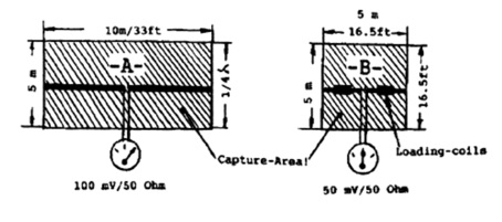
 The gain of an antenna A compared to an antenna B is equal to the capture area of antenna A compared to the capture area of antenna B.

The capture area of an antenna is determined by multiplying the antenna’s radiator length by 1/4 lambda. See Figures 1 and 2.

Example:

Antenna A Full-size 20m antenna (made from CU-wire 2mm/1/16″ O.D. +/-)
14 MHz dipole 1/2 lambda long: = 10m x 5m (1/4 lambda) = 50 sq meters

The capture area of a 20m dipole is 50 sq. meters or 540 sq. ft. The gain of this antenna is zero dB/d or 2.14 dB/i.

Antenna B Shortened 20m antenna (CU-wire 2mm/1/16″ O.D. w/big loading coils)
radiator length 5m/16.5ft., tuned by two loading coils to 14.2 MHz = 5m x 5m = 25 sq. meter.

The capture area of antenna B is 25sq. meters or 270 sq. ft. Note: Antenna B has only half the capture area of antenna A and is therefore able to “catch” only 50 percent of the electromagnetic field; e.g., 50mV, compared to 100 mV/50 Ohms. This means 6dB less gain for antenna B in comparison to antenna A.

These calculations require extremely low loss coils. Since there is no such thing as “no-loss coils,” an additional loss of typically 3 to 8 dB has to be taken into account.

Imagine how much power is wasted while using such antennas for receiving/transmitting.

The fact is, that only 250 Watts of the 1,000 Watts HF in your feedline are radiated — and this with “extremely-low-loss loading coils.”

These kinds of calculations can be found in all good antenna books, usually presented in the form of rather intimidating mathematical formulas. We hope the explanation above prove helpful to you.

Some Typical Examples

A typical vertical antenna with 0 (zero) dB/D gain in space is the Sleeven 1/2-wave dipole. Other 0 dB/D gain systems are 1/2-wave antennas such as the Zepp-Windom-Fuchs and vertical radiators such as Ground Plane-Discone (all in space).

Antennas shorter than 1/2-wavelength (tuned by a loading coil or traps) have much less gain. Typical: 1/2-wavelength = 1/4 $#34;power gain” ±loss of traps/coils. Following are some examples:

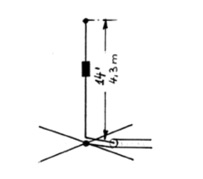
40 m GROUND PLANE 14 ft / 4.3 m high*, center loaded. Its efficiency is 7%. Its gain is -12 dB/D (compared to a full-size system without losses). This means that only 7 watts of a 100-watt signal will be radiated; 93 watts are wasted in this antenna.
See Ham Radio Magazine, Sept., 1982, P. 18 ff, by W1GV.

* A full-size 40 m 1/4 wavelength ground plane is 34.6 ft/10.5 m high; it has 0 dB/D gain.

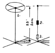
160 m GROUND PLANE 33 ft / 10 m high*, 12-Ohm ground

        Configuration                    Gain        Efficiency
1. Top loaded (big capacitor) -10 dB 10.0%
2. Center loaded coil -19 dB 1.2%
3. Base loaded coil -20 dB 1.0%


All the gains are compared to a full size* radiator and 0-Ohm ground. At #2 and #3, only 1 watt of a 100-watt signal will be radiated; 99 watts are wasted.

See Ham Radio Magazine, May, 1983, p. 36 ff, by W7DHD.
* A full-size 160 m 1/4 wavelength ground plane is 136 ft / 41 m high.; it has 0 dB/D gain.

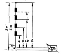
20 ft / 6 m long MULTIBAND ANTENNA 10-12-15-17-20 m Half-wave Zepp system. Open wire feedline or matchbox on “F”

Configuration      Gain         Efficiency
A=10 m -0.5 dB/D ~90%
B=12 m -2 dB/D ~63%
C=15 m -4 dB/D ~25%
D=17 m -6 dB/D ~15%
E=20 m -8 dB/D ~15%

Note: The traps were air coils, made from #9 copper wire, with air capacitors.

article originally available and copyright at sommerantennas.com website

1 thought on “Calculate your antenna gain”

  1. David Woolley says:
    March 9, 2021 at 12:52 pm

    Antenna gains are defined for transmission, not in terms of capture area. An ideal short dipole might have a lower capture area, and will have a lower radiation resistance, but its gain will not be reduced, except to the extent that you include resistive losses and the radiation resistance is too low compared with those. Even then the losses affect efficiency, not gain.

    On HF receive, particularly for the lower bands, what matters is whether the sky noise captured dominates the receiver front end noise. As long as it does, even efficiency doesn’t matter on HF. The sky noise captured depends on effective sky temperature (which is high on lower frequencies), and capture area (which even for short dipole is much higher than on VHF.

Leave a Reply

Your email address will not be published. Required fields are marked *

This site uses Akismet to reduce spam. Learn how your comment data is processed.

IW5EDI Simone

  • Licensed Amateur Radio operator in 1996 as IW5EDI, active member of ARI Firenze and ARRL
  • Class 1970, married with two childrens, love experimenting and antenna home-brewing. IT System Engineer, recently started having fun with morse code and Raspberry Pi


IW5EDI Simone


This Blog is mainly dedicated to Amateur Radio (Ham radio) and contains external articles and personal esperiences.

What is Amateur Radio ?
More Ham Radio Links


Blogroll

  • ARI Italian Amateur Radio Society 0
  • ARI Firenze ARI – Sezione di Firenze 0
  • ARRL Amateur Radio Relay League 0
  • DX Zone Ham Radio Internet Guide 0
  • DXSummit 0
  • DXWatch 0
  • eHam 0
  • Ham Radio Daily Ham Radio News 0
  • IW5EDI on QRZ.com My page on QRZ.com 0
  • Long Delayed Echoes 0

My Content

  • Antenna Projects 0
  • RadioAnnunci.it Mercatino Radioamatoriale 0

Categories

  • Articles (131)
    • Antenna Theory (13)
    • DXing (2)
    • How to (10)
    • shortwave (7)
  • Company and Products (1)
  • DXing (13)
    • QSLing (4)
  • Equipment (97)
    • Antenna (65)
    • Software Defined Radio (6)
  • Featured (28)
  • Ham Radio Events (25)
  • Ham Radio News (1)
  • Ham Radio Software (26)
  • HamRadio (94)
    • Ham Radio 2.0 (16)
    • How to (6)
    • Radio Scanning (6)
  • Homebrew (143)
    • HF Antennas (79)
    • Raspberry Pi (1)
    • UHF Antenna (16)
    • VHF Antennas (38)
  • Photos (4)
  • Short News (4)
  • Video (4)

Comments

  • Charles Mintoff on Ham Radio 2012
  • Roger Sparks, W7WKB on Petlowany Antennas by K6NO
  • Frank Barnes on Ameritron AL-80A restoration project
  • ken m3zkb on W5GI Mystery Antenna
  • Bobby on 5/8 Vertical Ground Plane antenna for 10 meters

RSS The DXZone.com

  • Top Amateur Radio Websites - Issue 2603
  • FT2: New Ultra-Fast Digital Mode Tested on HF
  • Top Amateur Radio Websites - Issue 2602
  • The G3LZR Tribander : The charm of the Impossible Antenna
  • Top Amateur Radio Websites - Issue 2601
  • Amateur Radio Clubs
  • Notes On Auto Tuners and Portable HF Antennas
  • DXtreme Monitor Log 14 - Radio Spectrum Monitoring Software
  • Sangean ATS-505 Receiver Review
  • Receiver Review: ICOM IC-R9000

Ham Radio Blog – IW5EDI Simone JN53OR

© 2026 IW5EDI Simone – Ham-Radio | Powered by Superbs Personal Blog theme