An article by VE3VDC LD Blake
Every radio amateur should build at least one antenna to prove to themselves they can improvise in an emergency. One of the easiest and quickest antennas to build is the Vertical Bazooka, which is made entirely from coaxial cable.
Beyond being extremely easy to build, these antennas have several nice features to recommend them:
- Total cost under $10.00cdn
- No coils needed.
- No ground radials.
- SWR under 2:1 across several megahertz
- Can be built as part of your feedline
- Can be coiled up and put in your car trunk.
- Performance like regular half-wave antennas.
- Self-supporting versions are easily built.
The antenna itself is an off-center fed vertical dipole made by flipping an electrical quarter wavelength of braid back over the outside of the coax. The center lead of the coax forms one half of the dipole and the braid forms the other. The resulting antenna has a low radiation pattern and an impedance of 55 – 60 ohms.
One of the more interesting features is the braid itself. By folding an electrical quarter wavelength of braid back over the insulated coax we are forming both a dipole and a “bazooka” (sleeve) balun, a coaxial 1:1 balun that greatly reduces feedline radiation. The braid side of the dipole ends up considerably shorter than the top element because of the interaction between the braid and the coax. The outer braid couples with the inner braid to form the balun and is thus affected by the velocity factor of the coax.
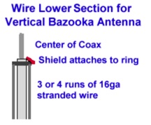
You can use the formulae in the diagram above to create Vertical Bazooka dipoles for any frequency. But please notice the formulas shown will deliberately start you off with the top section too long, so you will have to trim it for the best SWR.
You can build a mobile “emergency” version of the Vertical Bazooka by attaching a length of non-conductive cord (nylon line) to the top of the antenna. With a weight on the free end of your cord, you can simply toss it over any nearby support and hoist the antenna up into the air for use.
If you like you can also build a self-supporting version by sliding the finished antenna into a length of “Schedule 40” PVC plumbing pipe.
Building The Antenna
| Type | VF |
| RG-8 (poly) | 0.66 |
| RG-8 (foam) | 0.75 |
| RG-58 (poly) | 0.66 |
| RG-58 (foam) | 0.75 |
| RG-8X | 0.78 |
| RG-174 | 0.66 |
| RG-213 | 0.66 |
| RG-214 | 0.66 |
| RG-217 | 0.66 |
| RG-218 | 0.66 |
| RG-316 | 0.79 |
| LMR-195 | 0.83 |
| LMR-200 | 0.83 |
| LMR-240 | 0.83 |
| LMR-400 | 0.85 |
| LMR-500 | 0.85 |
| LMR-600 | 0.87 |
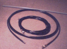
The only things you need to build a Vertical Bazooka are a length of coax, a connector to fit your radio and a length of heat shrinkable tubing. All these parts should be readily available from your local electronics parts or ham radio stores.
The antenna is made by removing the outer covering of the coax for the length of the top section, flipping the braid back over the outer covering of the bottom section and then trimming the braid to length. Once you have this done the task is that of trimming the upper section for best SWR.
The first step is to figure out the lengths of the various sections of the antenna. You will need to know the velocity factor of the coax you are using to get this right. A chart showing the VF of some of the more common 50 ohm cables is at the right.
- Calculate the overall length of the antenna using the formula:
Length = 15000 / center band frequency = Centimetres
For example: On 2 metres this gives us 15000/146 = 102.8 cm. - Calculate the length of the lower section:
Braid = (7500 / center band frequency) x VF = Centimetres
Eg. On 2 metres with RG-8x: (7500/146) x .78 = 40.1 cm. - To position the feedpoint we calculate:
Top = Length – Braid = Centimetres
Eg. On 2 metres with RG-8x: 102.8 – 40.1 = 62.7 cm
The first step in construction is to remove the outer jacket of the coax from the top section.
Measure down the length you calculated for the top section and make a cut around the coax jacket. Be very careful not to cut the braid. I find it helpful to fold the coax over my finger, to put stress on the jacket and cut very gently with a knife until the braid is visible in a small spot, then rotate the coax and cut again, until the entire circle is cut.
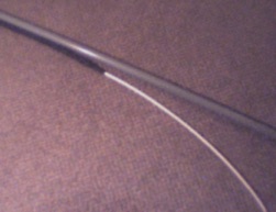
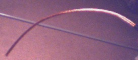
Now cut along the coax making a lengthwise slit in the outer jacket until you get to the end. Again be very careful not to slice the braid. Removing this section of jacket will expose the braid as shown on the left.
Now comes the part everyone has trouble with. We need to flip the braid back over the outer jacket of the coax.
 Starting at the end of the coax work the braid lose from the insulation over the inner conductor. This works like “chineese handcuffs” in that as you push back the braid will expand a bit and become free to move along the center insulator.
 Once you have the braid free to move, simply grab it an inch or two above the bottom of the exposed part and push it back over the coax in short sections. Once you get the first section over, move down a bit and continue with the next. Once you get it started, it will actually go quite easily.
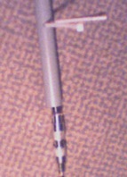
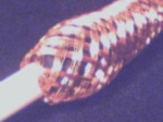
 On the right we see a close-up of the feedpoint of the antenna. This is actually at the end of the outer jacket and was formed when you flipped the braid over.
Now smooth the braid down tightly over the outer jacket and put a bit of tape at the bottom to hold it in place.
The next step is to trim the braid to length. Measure down from the feedpoint (the top of the braid) and put a tight band of tape around the braid so that it’s bottom edge is where you want to cut. Now using fine wire clippers, clip the braid to the final length you calculated.
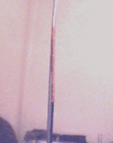
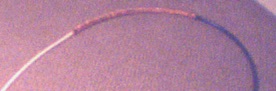
On the left we see a shot of the antenna with the bottom section trimmed to length. The formulas we used get the length of the braid very close to what it needs to be –and it’s not terribly critical– so this would be a good time to cut a length of heatshrink to cover the feedpoint and braid with a few centimetres extra on each end. You can use a heat gun or blow drier to tighten it into place.
If you are building an emergency version of the Vertical Bazooka you can make the remaining length of coax (the feedline) almost any reasonable length. If you are building a stand alone version you will want to leave enough below the braid to attach a connector once it’s in it’s housing.
Finally install a connector appropriate to your radio or feedline. For emergency versions that will be used with a HT you can use BNC or SMA connectors. For use with a mobile radio, a PL259 will likely be needed. For stand alone versions, a PL259 and a double female coupler, is probably the best bet.
That’s it, the antenna is all ready for it’s tuneup…
Tuning The Vertical Bazooka
The Vertical Bazooka is easily tuned by clipping short sections from the end of the exposed center conductor of the antenna.
There are, however, some precautions you must observe. This is a dipole, which means it has easily disturbed high impedance nodes at both the tip of the top section and the bottom of the braid. It is an absolute necessity that you get the antenna out into a clear area for tuning. If at all possible, you want at least 1/2 wavelength of clear space all around the antenna. More is better.
Probably the best strategy is to tape the antenna to the side of a length of white PVC tubing so that you can stand it up during tests and tilt it over to clip the top section. Alternatively you can temporarily attach a non-conductive cord and hoist the antenna up and down from a tree branch or clothesline, being careful of the clearance requirements.
Also please note, these clearance requirements include you as your body capacitance can upset the readings. If you’re building an emergency version it’s no problem as you can simply play out the feedline and work from the other end. If you’re working on a self-supporting version you will need to add a length of feedline to enable you to get back from it during tests.
Once you have the antenna in a testing position, take SWR readings at the top and the bottom of the band you’ve cut the antenna for. Your first readings will (hopefully) be terrible, with the bottom of the band reading a little bit better than the top. This will tell you the antenna is too long… so you’re set to begin trimming.
With the formulas used it is very unlikely the antenna will start out too short.
You should note that you will not likely get a “flat match” or 1:1 SWR from this antenna. It’s feedpoint impedance varies from 55 to 60 ohms, so you should be happy with anything under 1.5:1.
Assuming the antenna starts out too long:
- Clip a few millimetres from the free end of the top section.
- Repeat your band edge measurements.
- If the low end of the band is still better than the high end, go to step 1.
- If the low end and high end readings are equal, you are done.
As you are clipping, the SWR at the low end of the band may come down then start to move back up. That’s ok, it’s just the antenna’s resonant frequency passing the low end of the band. Once you complete the clip and test cycle the resonant frequency should be near center band and you should have an SWR curve that has equal readings at both band ends and a somewhat lower reading in the center.
Deploying the Antenna
So, now that you have it all tuned up, the next step is deployment.
If you are working on an emergency “coil up” version of the antenna you will want to add a good length of non-conductive cord, such as nylon twine or light rope to the antenna with a small weight at the loose end. This will let you spin the weight up on the end of the line and toss it over a tree branch (or other handy hanging point) and then use the line to pull the antenna up into operating position.
 The best way to affix such a line is to solder a ring terminal or wire loop onto the end of the top section of the antenna. The trick is to do this without changing the length of the antenna.
Strip away the center lead’s insulation so that you can slide the ring terminal on far enough to get the top of the ring even with the end of the wire. Slide on the ring terminal and solder it into place, then trim the wire out of the way of the ring terminal’s opening.
 If you’re working on a self-supporting version of the Vertical Bazooka you will need a piece of white PVC “schedule 40″ plumbing pipe long enough to make a radome with allowances for a mounting gap and attachment to a mast pipe. This will need to be large enough to hold the coax but not so large as to let it sag inside. 1/2″ PVC will hold antennas made from RG-8x and RG-58 nicely. For RG-8 or other large coaxes you can use 3/4”.
The length of the radome can be a problem at lower frequencies. As the length increases so does it’s tendency to sag or move about excessively in the wind. About the practical limit with PVC radomes is 6 metres (54mhz).
The mounting gap cannot be ignored. You will need a gap between the bottom of the antenna and the mounting structure at least the length of the braid section if the antenna is not to be detuned by the mastpipe. Longer is better, within reason.
There are several methods you can use to secure the antenna inside the radome. My suggestion would be to attach the ring terminal, as above, then drill a small hole at the top of the pipe and catch the ring in a wire-tie. No matter what method you use you do have to take some precaution to make sure it’s not going to find it’s way out.
And, of course, don’t forget to put a weather cap on top of the radome.
Usage and Conclusions
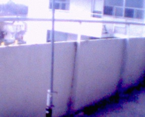
I’ve used the Vertical Bazooka both on my balcony and as a backpack antenna on a recent day trip with my bicycle. I find it’s performance to be about average; that is, what you’d expect from a dipole. When hanging from a tree branch it will open repeaters 25 and 30km away on my HT’s medium power setting. From my balcony that range is almost doubled.
The SWR of the antenna isn’t bad. My 2 meter versions came in at about 1.3:1 on each end of the band, about 1.2:1 in the center.
I made this for a 6 Meter vertical from your instructions and it works fine.
I had built one back in 1964 for use on 11 Meter CB when I was 16, for the annual Maryland Boy Scouts Camporee held at Ft. George G. Meade near Baltimore, Maryland. I didn’t have a clue then as to what I was doing, and for sure I don’t remember where I got the plans. Ha!
These make excellent temporary “hang ’em from a tree” style antennas.
Hello Simone,
Seen the same basic project done with the coax fed up through a length of ~3cm copper tubing which then has an end-cap (either an over the pipe cap, or simply a flat piece of plate copper) soldered to then end, and then fitted with an SO-239 on the top to receive a PL-259 with the radiator soldered into it.
I should be taking delivery of my new NanoVNA-F today and being an Apartment dweller, I need to not only have a ‘room corner’ array for 2m, but also need to brew one for the FM-BC band of the Stereo.
Will your measurements and calculations for this Bazooka-Braid Coaxial Vertical be close to what I’m thinking of with the copper tubing ? I understand it will be somewhat more $$ – what with the increase in copper prices, and I’m curious to know if you think choosing a larger diameter tubing (maybe 7-8cm) will increase the SWR bandwidth of the antenna. I expect a lot of this to be test-n-trim process…
Of course the FM-BC version would need to be 75ohm feedpoint matched for the Stereo receiver, so would that simply entail using RG-6 for the construction, instead of RG-8 for the 2m array, to create the different array impedance ?
By the completion of this project, I should know much more about using my new ‘toy’ and about reading Smith Charts.. 😉
NOTE: I also need to do this with an omni-directional array for GMRS (462-467mc), in order to get back on the air with those folks…
And what about, dare I dream it, Gain with this format ?
The GMRS repeaters are much lower level than the 2m ones.
Or should expectations be for close to ‘unity’ with this (aka 1/4wl with radials) ?
How would going to a 5/8wl radiator and inserting a loading coil at the top of the bazooka match work out ? Just brain-storming here… Thanks !
73 4 now,
KB6LWN – Bruce
Just a poor ham!
Love it! I have it currently mounted Horizontally (more directive than vertical) to catch VHF/UHF for TV reception. Don’t miss the balun stealing my Milliamps. It is for reception only. Wideband – stations range from 200MHz to 600MHz. The farthest tower is 30 miles away. I will be inserting the antenna into a water tight PVC tube and setting it outside approximately 25 feet above ground and I hope to be able to get good reception with it mounted vertically. Great job, thank you again!
Michael
What about uhf band with this dimensions?
I made 4 of these antennas for 127.5 the center of the aircraft COM band. I tested them and tuned them with a NanoVNA and could not get the SWR below 2::1. @ 127.5.and made another but gave up.
Perhaps the cheap RG58 I used did not have the “foam” velocity factor according to the chart. It looked like foam not polyethylene.
Del, K1UHF
Nice! We used several of just the folded braid portions as hidden receive-only antennas for wireless microphones. I believed my chief engineer was insane for this, but his theory and design were sound. They performed quite well and no one was the wiser when we had 4 hidden in plain sight for over 10 years! I’m anxious to try this out on my ham rig!