Striking a Balance
When you connect centre fed antennas, like dipoles, Vs, triangles, yagis, rhombics, loops and so on, to coaxial cable, unless care is taken, it is not difficult to end up with feeder radiation. Not only can the loss in power be quite significant, but the radiation characteristics of the antenna system will also be seriously compromised.
As the feedline becomes part of the antenna, currents can flow from the line into the mains and on TV cables, metal masts and yagi booms, causing a variety of EMC problems that can be very difficult to trace. Frequently these problems are simply due to unbalance – and the solution is the humble balun.
Tests carried out in an anechoic chamber to determine the affects of unbalance on radiation patterns of a half wave dipole (published April, 1980 in QST) show just how serious this can be and how important the function of the balun is in achieving predictable patterns.
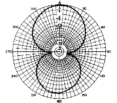
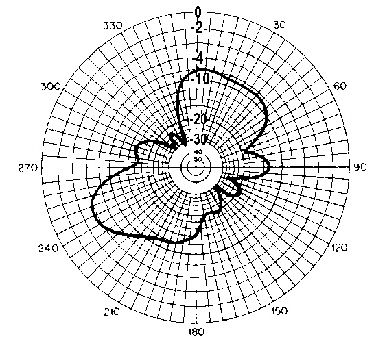
Although these results are indicative only and will vary according to each individual case, and whether receiving or transmitting, the 5dB drop in peak amplitude in the receiving pattern of the unbalanced balanless antenna is significant.
Moreover, in real life, objects in the vicinity of an antenna will exert their influence on the radiation pattern as signals are bounced off them and re-radiated. So, how they are installed is crucial if the system is to be balanced and the desired performance achieved, as well as the quality and efficiency of the balun itself.
If an antenna system is fed at centre with a parallel conductor line (provided that correct installation procedures are followed) balance will be maintained with currents in equal and opposite phase cancelling each other out.
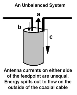
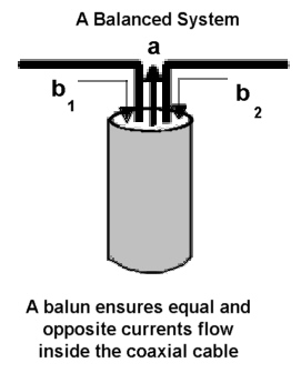
When the connection is to a coaxial cable this cannot occur because currents flowing inside the cable from the connection to the inner conductor are separated from those flowing on the outside from the connection to the shield, and the result is unbalance causing feeder radiation. However, if the two electrical circuit elements (antenna and coaxial cable) are coupled using a balan, balance will be maintained.
Essentially there are two types of balun, the Choke balun and the Transformer balun, each operating in a different way to achieve a similar end. The name derives from balance to unbalanced. Each aims to provide a solution to the problem but in quite different ways.
| The Choke balun aims to choke the current off at the feed point by creating a large series impedance on the outside of the cable thus preventing currents from flowing. It can be as simple as a few turns of cable in a loop, cable wound around a toroid or ferrite or fed through ferrite tubes or beads to form a sleeve. If the installation is asymmetrical, however, the choke balun may not be able to prevent surface currents from electromagnetic coupling further down the cable, especially if the feedline length is resonant. Therefore if surface current flow persists, more chokes are required at intervals down the feedline. |
Adding a choke will not normally affect the VSWR, as it only affects the outside of the cable and cannot influence impedance inside the cable. However unbalance will, as the feeder becomes part of the antenna system and load impedance is altered. The choke merely suppresses surface currents and makes no attempt to create balance.
| The Transformer balun, on the other hand, acts to create balance by forcing equal and opposite currents at either side of the feedpoint, through closely coupled windings within the transformer. With the transformer balun it is also possible to alter impedance by a factor, either up or down. As with the choke balun quality and efficiency are all important. Unwanted resonances due to distributed capacitance between the turns of the transformer can induce impedance mismatch and unbalance, as can leakage inductance from loose coupling between windings. |
For total balance to be achieved on either side of the feedpoint, installation and environmental factors must also be taken into account. If any unbalance remains, the transformer balun will not suppress any resulting surface currents. However, these can be negated by the use of choke baluns further down the line.
Acceptable performance standard at the edges of the operating band are normally: balance within 1dB, a phase angle of 180 +/- 10 degrees and a VSWR of less than 1.5 into a balanced load. If loads are inaccurately matched, especially at HF where the length of the coiled transmission line may approach an electrical ¼ wave, the balun cannot compensate and balun performance will be adversely affected.
Environmental factors influencing balance are most critical at HF frequencies. At VHF/UHF frequencies, however, it is the lengths of connecting wires and necessary gap at the centre of a dipole that cause difficulties, impeding creation of a symmetrical junction at the feedpoint as they are often significant fractions of a wavelength.
In practical terms, it is always important to maintain balance in the system. Where an antenna is located in close proximity to buildings unbalance can occur leading to feeder radiation and EMC problems (see diagram). If the antenna end conditions are different, a balanced antenna can become unbalanced negating the effects of a balun. If one end is connected to a metal building, the metal structure can act like a huge capacitor seriously compromising the desired antenna design.
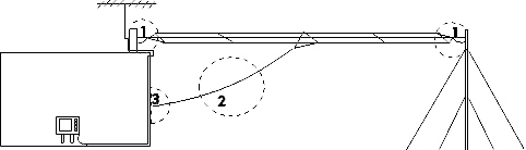
Feeder Radiation & EMC
| Antenna end conditions differ creating unbalance Feeder radiation due to angle of feedline Radiation from feedline reacts with household wiring causing EMC Installation is complicated by TV wiring. |
The centre feedline should always be at right angles to the wire, otherwise energy can flow on the outside of the coaxial cable due to the fact that it is running almost in the same plane as the antenna wire. The coaxial cable will then no longer act as a good screen. Energy will be conducted into the building reacting with the house wiring (and vice versa) causing EMC problems and noise interference in receive mode.
While the balun may seem insignificant in the larger more complicated picture, the smallest link in the chain, it is worthwhile remembering that its function is of critical importance. Tracking down problems that arise from unbalance can waste a great deal of time and money. Knowing your centre fed system has been designed and built to give you predictable balanced performance leaves you only the installation to worry about.
Article originally available at http://www.moonraker.com.au/techni/feeders.htm