
4 Element Yagi Building

This article contains discussion of all the different antenna principles previously described elsewhere on this website. A thorough reading and understanding of the other sections are necessary to comprehend all the terms used on this page. It is not necessary to understand all the terms and theories described to build and enjoy this 4 element Yagi however. This particular section is geared towards the “freeband” CB operator – that is one who uses CB channels above (or below) the standard 40 CB channels. These CB “channels” are not legal for use in the United States – but they are quite popular any ways! The frequencies mentioned in this article are legal CB channels in some countries, check your local laws and act responsibly. This article shines little light on finding cheap aluminum or alternative methods of construction materials for Yagi antennas. It is also devoid of information on the physical design of Yagis. Sad but true, useable aluminum tubing in small quantities is expensive. And the physical design of Yagis is a subject beyond my limitations! What this article does do is provide a truly optimized 4 element Yagi design for the 11 meter “freeband” DX operator. Careful consideration was given the operating frequency and “rejection” needs of most 11 meter freeband DXers (CB operators who communicate with other CB operators more than 150 miles away).
Over the past 5 years, I have gotten many emails regarding the Yagi . antenna. They seem to be more popular than the other types of beams. I have built my share of Yagi antennas, but in the last five years (since 1997) there has been tremendous amounts of study done on the Yagi antenna using computer modeling. Since the desktop computer has become so powerful, serious computer modeling of antennas has been put in the reach of many amateur antenna experimenters and this has lead to very optimized versions of the Yagi antenna. These computer optimized Yagi’s feature much “cleaner” patterns – this means the overall forward gain hasn’t increased significantly, but the Front to Back and Front to Rear ratios have really been improved. So trading your old 1970s Hy-Gain Yagi for a brand spanking new computer optimized Yagi antenna won’t yield you a new monster signal – but will certainly increase your ability to reject signals coming from unwanted directions. Most times this is more important that forward gain itself because the CB bands are so crowded that being able to reduce some offending stations signal is more important (than forward gain).
A few words on computer modeling of antennas. Most amateur antenna modelers (like me) are using Numerical Electromagnetics Code or NEC-2 for short. A complete history of NEC-2 may be found at http://www.nec2.org/. NEC-2 is basically a computer program (or application if you like) that is able to simulate the electromagnetic response of antennas and other metal structures on the computer. This means you are able to build a antenna virtually on the computer screen and see its exact performance without even building the antenna. Imagine being able to change antenna length with a few clicks of the mouse and see its effect immediately! NEC-2 has a few limitations but is considered highly accurate if the antenna is built exactly the way it was specified on the computer. By accurate I mean the computer predicted performance of the modeled antenna closely matches the performance of the antenna if it was constructed and tested “in the real world”.
The study of Yagi antennas on the computer has produced some outstanding new Yagi designs and shed some light on the key dimensions of Yagi performance. In the past, gain was really equated with the number of elements a Yagi had. Computer modeling has shown that boom length is the real factor that determines gain. For instance, merely shoving more elements on a boom will have little to no effect on gain. The boom length must be allowed to expand. A classic example of this is you find many CB antenna that place too many elements on a given boom length. For instance, you often find makers of CB antennas cramming 5 elements onto a 20 foot boom. If you study this design on the computer, you’ll find that 4 elements on the 20 foot boom will work the same, if not better. Knowing this, it becomes obvious that it is more important to consider the length of the boom, rather than the number of elements a Yagi has, to gauge performance. Front to Back has really improved as well. Typical Front to Back ratios on the the “cut and try it” Yagi were about 15 dB – 20 dB (max) in the real world. A carefully designed antenna today can see as much as 30 dB – 35 dB of “rejection” (CBer term for “Front to Back ratio”). Some Yagis antennas have “corner nulls” (the back corners of the beam pattern) that can reach numbers as high as -70 dB! Computer modeling also puts to rest the idea that Front to Back (F/B) ratio increases with every element you add (commonly advertised by antenna manufacturers). In fact – you can tune a 3 element Yagi to have as much Front to Back ratio as a 8 element Yagi! Gain usually goes up with a longer boom, but the Front to Back ratio can be tuned up to about 30 dB on almost any multi-element Yagi.
These days the CB band is really crowded. There are many guys out there just jamming the channels – particularly 27.555Mhz (USB). The best thing a serious DXer can do is to build a antenna with a very high Front to Back (F/B) or Front to Rear (F/R) ratio to help knock down these annoying station’s signals (besides completely ignoring them). This also serves to reduce multipath fading that occurs during a DX contact. I set out to design a antenna with the “cleanest” pattern, with the best F/R ratio I could develop and cover from 27.405Mhz – 27.855Mhz with with an optimum performance emphasis on 27.555Mhz . Most of the offending stations I hear (on 27.555Mhz) come from due West, therefore I designed a 4 element Yagi to have the greatest “rejection” to the west when I have the antenna pointed towards the North East (see figure 1). The initial design was based on a 4 element Yagi for 24Mhz (12 Meter Ham Band) from the 19th edition of the ARRL Antenna Book (which also contains great detail on the physical construction of Yagi antennas). I remodeled this antenna for 27.555Mhz using NEC-2, specifically using the computer software “NEC Win Plus”, by Nittany-Scientific and Multi-NEC, by Dan Maguire (Amateur Radio Operator, AC6LA).
Figure 1 Coming Soon…
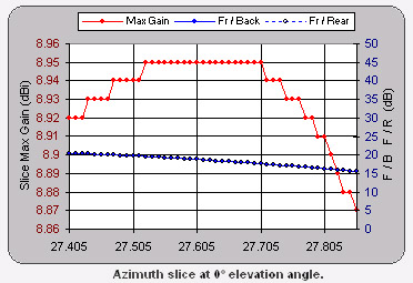
The boom length is short – just under 14 feet long, which is short compared to the common length of 16 feet most used for traditional 4 element Yagi for CB. To make construction simple, I ordered up a MaCo 4 element Yagi M104C . For around 160$US (direct from MaCo), it represents a fair value. You are getting everything you need, including the gamma matching section, which is a pain to homebrew yourself. The stock MaCo 4 element is a pretty average performer out of the box. With around 9 dBi of gain and a F/B around 20 dB, its performance is very typical – see Figure 2.

Frequently the freeband operator takes a beam antenna made for the regular CB channels (26.965Mhz – 27.405Mhz) and uses the dimensions straight from the owners manual. Then the gamma match is adjusted for the best SWR on the frequency of interest. This results in very poor “rejection”, because the beam antenna is being operated so far off its designed center frequency (see Figure 3). This is one reason so many people have resorted to money making snake oil fixes on their beams, such as extra “rejection wires”. The correct fix is to rescale (actually remodeled) the antenna design on the computer for the new center design frequency to insure a useable F/B ratio over the new operating range. Figure 4 shows the performance data for the M104C operating on the “freeband”.

With some adjustment of the boom length, element spacing and element length this antenna is transformed into a very potent performer, due to its new found ability to “reject” signals from unwanted directions better. See new radiation pattern in Figure 5. My NEC-2 computer optimized antenna, that I call the “Freeband 4”, sacrifices about .5 dB over the 16 foot boom length. It is about 1 dB down over a 4 element Yagi on a 20 foot boom. The loss in forward gain is barely perceptible signal wise (remember 1db is roughly only 1/6th of 1 S Unit). The increase in rear signal rejection is amazing! “Back corner” rejection in the real world lives up to the computer predicted values – I can reduce my neighbors 40 dB over S9 signal (that is “way, way in the red” on the signal meter) down to nothing! The shorter boom length is a bonus too – most antenna mounts and rotors can handle a 13 foot – 14 foot boom. Its a mere 4 foot longer than the common 9 foot boom length used for 3 element Yagis. This antenna provides about 1 dB of gain over the tradition 3 element Yagi on a 9 foot boom and as previously noted, probably has a much more usable rear rejection.


The taper schedule of this antenna must be followed exactly for the performance to match the stated figures – “close enough” will yield disappointing results. This is the biggest mistake made by computer modelers – not accurately building the model as entered on the computer. Also limitations in NEC-2 must be accounted for. This antenna can not simply be lengthened for regular CB use (26.965Mhz – 27.405Mhz) – the carefully designed pattern will be lost. I haven’t reworked the design for the standard CB channels yet. Drop me an email if you are interested. See Figure 7 for the dimensions.

This antenna was design to be operated in the horizontal position (producing horizontal polarization). All the above paragraphs describing antenna performance are strictly referring to this design in the horizontal position. This is the most common polarization used by DXers . The pattern of this design in the vertical position is shown in Figure 8. I display this pattern here just to show the difference that occurs if the Yagi is operated in the vertical position. No attempt whatsoever was made to optimize this antenna in the vertical position. You can see there is a *huge* change in the pattern when the antenna is operated in the vertical position – this fact is rarely pointed out in books on antennas for DXing because they all assume the horizontal position will be used. This is not always true on the 11 meter CB band. The 4 element Yagi in the horizontal position does provide better all around F/R (“rejection”) than it does in the vertical position. Again, I wouldn’t recommend you switch to my design over your current design if you need to use it in the vertical position – I can’t promise better performance.

A final word about computer modeling of antennas. If you understand and enjoy building antennas, computer modeling is the next logical step for the experimenter to take. There are quite a few references out there you should check out, the subject is covered well on other websites, such as http://www.cebik.com/.
Here is the owners manual for the MaCo 4 element Yagi M104C : http://www.majestic-comm.com/assembly/SUPPORT/M104C.PDF. The owners manual gives all the stock dimensions of the antennas and shows assembly detail.
Here is a link to all of MaCo’s antennas owners manuals: http://www.majestic-comm.com/assembly/index.htm .
If you build this antenna – be sure to let me know how it works out for you! 73s Scott
Article originally available at http://signalengineering.com:80/ultimate/4_element_yagi.html
I want to build a 4 element CB antenna – direct feed – Is this formula OK my needs ?
Also is this using heavy wall are thin wall aluminum ?
Thank you
Arkieguide
Hi Simone can you help me to optimize my 4 element Maco yagi for my son who talks on 11 meters. Thank you..
Simone, looks like you have done your homework, appreciate it.
I would like some info on building a 4 element (off the M104 kit) as mentioned in your article. As i do go to 27.555 my normal channel is 27.385 and the article mentions the very specific measurement for .555 and was wondering if have had a chance to calculate them for 27.3850?
thanks Mark
can you optimize a Maco 104c that works on 11 meters
Thanks Ed
Simone, I am also looking for CB measurements. Ran these measurements in Yagimax 311 and came up with not great results. Spring is still a ways off to be climbing the tower here in Northern Ontario.
Hi Scott,
Very interesting article, thank you for sharing your study with the rest of the world. 🙂
I am curious about the exact boom length, I am assuming from the article and the dimension listed it is 13′-14′. Can you please share with us the exact boom length as I am interested in building this yagi?
73 Happy dxing!
Jerry
So I have this maco 104c and I have 20′ boom my question is if I am strictly on cb band and I have 5 elements currently what should my antanna boom be and how many elements should I use for maximum performance.
Good day,
I am in the market to build a new 11 meter antenna for primary channel 27.365mhz. Did you ever make a design for normal 11 meter frequency. I want to feed it directly with coax and a balun will this total defeat your design. 73
would love to see this 4 element design for 27.185. i have a sirio 4 element that is damaged and was already thinking about making it a three element. any suggestions? thanks for your time
Hi. I would like to build a 6 or 7 element Yagi for cb use on 11 meters hoping to achieve 18db forward gain. Are you willing to design and sell me the specs please?. Thank you much
Hi therewould you have plans and sizes for a 4 element yahoo beam for 27 mhz , I waiting make one but I can only find plane for a 3 element beam , hope to hear for you soon . Thank you
Regards
Petar
Hi there do you have any plans and sizes for a 27 mhz 4 element yagi beam . Thank you
Good evening Simone do you have a design for a 26 to 27 mhz 4 element gamma match yagi beam , hope to hear from you soon
Regards
Petar
I built this antenna in Jamaica (23 Div) and got great reviews. Been off the air a number of years and now coming back. Pulling down the antenna to transfer to my new location and was wondering if there were any amendments since this design that can make this a bit more wide banded?
Gooday to you.
Can this antenna be matched using a hair pin match, if so what ajustments are needs to be done.
Best reguard.
Jeffrey
I would like to build a 4 element yagi antenna what is the booth Lane for 11 m for CB radio