Skip to content

IW5EDI Simone – Ham-Radio

Amateur Radio made in Italy

Menu
  • About me
    • QSL info
    • Log Book OnLine
    • What I Hear
    • Live Stream
    • Perchè (Why) in English ?
    • Contact me
    • Privacy info
  • Software
    • Ham Radio Deluxe 5.2
    • IP-Sound
    • OscillometerXZ
    • YO Yagi Optimizer
    • HamAlyzer 2.8
    • ERP Calculator
    • 59+ software
    • Magnetic Loop Calculator
    • MeterMate
    • UDY 2 Voice Keyer
  • Ham Radio
    • Beginners Guide to Ham Radio
    • Direct QSLing from Italy
    • Foreign Ham Operations in Italy
    • Tourist Ham Radio in Italy
    • Frequency List
    • Metric Conversion Table
    • Sound Card Interfacing for RTTY, PSK31, and SSTV
  • Technical Articles
    • Microphone Connections
    • A low cost 600 watt ultra-linear amplifier
    • VE7AVV – YAESU FL-2100Z Amplifier Repairs
    • Mic Wiring – Ham Radio
    • Homebrewing a balun
    • Grounding Concepts
    • HF Scanning frequencies
    • Wi-FI: Measuring network throughput
    • Determining RFI problems in mobile
    • Hidden and stealth antennas
  • Antennas
    • 144 / 430 Dual Band J-pole antenna
    • 10 Meter 4 Element Quad Antenna
    • 144 Mhz Magnetic Loop Antenna
    • A “loopy” Loop Loaded Vertical
    • W5GI Mystery Antenna
    • A Multiband Dipole
    • Build a W3DZZ Antenna
    • A portable 2-element VHF yagi
    • Assembling GAP Titan DX Antenna
    • The Galaxy Dipole
    • Pfeiffer Maltese Quad Antenna System
    • Magic Anti-Jamming antenna
    • D3+ High Performance Antennas
    • EH Antenna for 40 and 20 meters
    • Homebrew G5RV
    • 40 meter mini Moxon Antenna
    • EH Antenna for 10 meter
    • Quad and ModQuad Antenna
    • Inverted U antenna for 160 meters
    • 6 Band HF Windom antenna
    • The Bazooka Antenna
    • Antennas for HF mobile operation
    • Inverted L Antenna for Low Bands
    • Your first dipole
    • Remote control Antenna Switch
    • The gin pole
    • Hexbeam antenna setup
    • W4TI Rotor Installation
Menu
Ground

Performance Tips – Earth Ground

Posted on March 4, 2018 by Simone

Earth Ground

Most of us overlook the importance of hooking good earth grounds to our antennas and our radios. Some think if lightning hits, its going to do what it wants to do. Probably right! Lightning protection is not why I am stressing the earth ground. Good earth grounds serve two purposes. One they protect against lightning (by routing current to the ground instead of our radios). Secondly, they discharge stray RF energy. There are a few things this does for us. First, it makes our receiver quieter (less static). Secondly it prevents RF from building up on the station equipment and distorting our audio (So many CBers have this problem!). Have you every heard someone who’s audio would distort when they would talk? The number one cause of this is strong RF currents running on the radio chassis and mic (more power and the problem gets worse!). Also grounding stray RF energy cuts down on interference to TVs, Phones etc. Plus, if you are using a vertical antenna (1/2,5/8 Wave) you can improve the performance by lowering the angle of radiation by using ground rods and radials running on the surface of the earth under your antenna. This is a total must if you are co-phasing verticals.

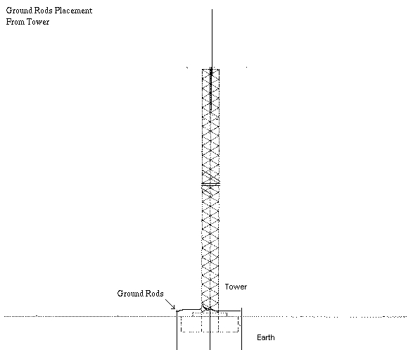
So what constitutes a good ground? Well, it depends on a few things. First, inspect the soil where you have your ground rods (or will you will be putting them). If your soil is rocky or sandy, you better buy a few ground rods and a bag of rock salt. Rocky and sandy soil is a poor conductor and has a high resistance to ground. If you soil is high in mineral or ash content (nice dark top soil deep down for many feet) then you have a nice low resistance to ground. There are two places where you will need to a make good ground. One from the antenna, so the ground should be directly (or as close as possible) underneath the antenna. Figure 1 shows where to place the ground rods around your tower, but if you have your antennas mounted on your roof, still run a wire to three ground rods shaped like a triangle.


Ground
Figure 1 – Three ground rods located around the base of the tower. The ground wire runs down the tower from the antenna, and splits into three, and runs to each ground rod. Solder the wires to the rods!

The other ground should run from the back of your radio chassis. Actually, all the station equipment should be grounded together with a heavy copper wire (coax braid is good). This should run to a ground as short as possible, preferable out the window to the ground directly. You must keep this ground under 9ft long (102″) or the effect of a long wire will impede the RF from grounding. If you must have a longer ground wire (really, try not to, this is important), run a separate wire off the back of the radio (where the normal ground is hooked) that is 102″ inches long. just let the wire hang to the floor and then run it across the floor (don’t roll it up). This is called a “counterpoise”. You should have three ground rods outside the window, shaped like a triangle like you have around your tower.

If your soil is rocky or sandy, drive your ground rods, pull them back out and dump the rock salt into the holes where the ground rods go. Then, fill the holes up with water to dilute the salt and let it flow in the ground surrounding the rods. This will greatly improve the conductivity of the earth. Remember to replenish the salt ever year, it disapates into the ground over time. Ground rods should be copper about 6 – 8 feet long. You should have at least three ground rods, located about 6 feet from each other. You will need at least 6 ground rods in total, 3 for the antenna and the other 3 for the radio ground. Solder the wires onto the ground rods (to prevent static ground noise).

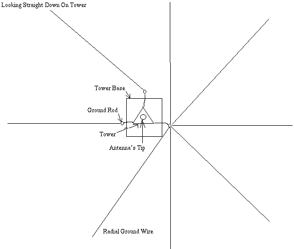
If the antenna you are using is a vertical, it would be helpful to place “radials” off of one of the ground rods. You do this by taking a shovel and driving the tip into the ground, rock it back and forth opening up a V shape in the soil (no deeper than 1 inch). Do this at least 8 directions from one of the ground rods (if possible). Radials should be as longs as possible (36 feet is best). Drop the radial wire into the channels you built with the shovel and stomp the channel shut with your foot or the shovel to seal the wire into the ground (to hold it down and so you do nail it with your lawn mower!). This is a great way to improve the DX capability of the vertical! Figure 2 shows a view looking straight down on the tower. You can see how the radials should lay.

Ground Radials
Figure 2 – Looking straight down on tower. You can see the radials, but after you install them, they should be buried under the ground about 1/2 inch (no more than 1 inch deep). This will improve the radiation pattern of the vertical antenna. If you are not using a vertical antenna, just go with the three ground rods. Make sure they are about six feet away from each other.


The connection to your antennas should be a good one with the largest practical conductor size. You should hook the ground close to or on the shield of the coax (on the collar of the PL-259). Connect the ground wire to the chassis of you radio, hooking it firmly to metal. If the connection is loose, it will cause more static noise on your receiver! Do not expect to notice a huge difference (or a immediately detectable difference) from doing this. But remember, when you are trying to talk to a DX station with the faintest signal, even that slight bit means hearing or not hearing that DX station.


Article by Scott 2rp789 originally available at http://signalengineering.com:80/ultimate/earth_ground.html

Leave a Reply

Your email address will not be published. Required fields are marked *

This site uses Akismet to reduce spam. Learn how your comment data is processed.

IW5EDI Simone

  • Licensed Amateur Radio operator in 1996 as IW5EDI, active member of ARI Firenze and ARRL
  • Class 1970, married with two childrens, love experimenting and antenna home-brewing. IT System Engineer, recently started having fun with morse code and Raspberry Pi


IW5EDI Simone


This Blog is mainly dedicated to Amateur Radio (Ham radio) and contains external articles and personal esperiences.

What is Amateur Radio ?
More Ham Radio Links


Blogroll

  • ARI Italian Amateur Radio Society 0
  • ARI Firenze ARI – Sezione di Firenze 0
  • ARRL Amateur Radio Relay League 0
  • DX Zone Ham Radio Internet Guide 0
  • DXSummit 0
  • DXWatch 0
  • eHam 0
  • Ham Radio Daily Ham Radio News 0
  • IW5EDI on QRZ.com My page on QRZ.com 0
  • Long Delayed Echoes 0

My Content

  • Antenna Projects 0
  • RadioAnnunci.it Mercatino Radioamatoriale 0

Categories

  • Articles (131)
    • Antenna Theory (13)
    • DXing (2)
    • How to (10)
    • shortwave (7)
  • Company and Products (1)
  • DXing (13)
    • QSLing (4)
  • Equipment (97)
    • Antenna (65)
    • Software Defined Radio (6)
  • Featured (28)
  • Ham Radio Events (25)
  • Ham Radio News (1)
  • Ham Radio Software (26)
  • HamRadio (94)
    • Ham Radio 2.0 (16)
    • How to (6)
    • Radio Scanning (6)
  • Homebrew (142)
    • HF Antennas (78)
    • Raspberry Pi (1)
    • UHF Antenna (16)
    • VHF Antennas (38)
  • Photos (4)
  • Short News (4)
  • Video (4)

Comments

  • Charles Mintoff on Ham Radio 2012
  • Roger Sparks, W7WKB on Petlowany Antennas by K6NO
  • Frank Barnes on Ameritron AL-80A restoration project
  • ken m3zkb on W5GI Mystery Antenna
  • Bobby on 5/8 Vertical Ground Plane antenna for 10 meters

RSS The DXZone.com

  • Top Amateur Radio Websites - Issue 2603
  • FT2: New Ultra-Fast Digital Mode Tested on HF
  • Top Amateur Radio Websites - Issue 2602
  • The G3LZR Tribander : The charm of the Impossible Antenna
  • Top Amateur Radio Websites - Issue 2601
  • Amateur Radio Clubs
  • Shrunken Quad
  • DIY Magnetic Loop Antenna Tutorial with Remote Tuning System
  • HF Beacon Tracker: Real-Time 3D Propagation Visualization
  • WSJT-X FT2 fork Decodium

Ham Radio Blog – IW5EDI Simone JN53OR

© 2026 IW5EDI Simone – Ham-Radio | Powered by Superbs Personal Blog theme