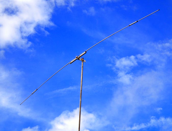
 There are quite a few ways to make full-sized dipoles that can be rotated.
How you attack this mostly depends upon what band is to be covered (basically how big) and whether the wire is to be horizontal or is permitted to slope downward from a central post.
In the horizontal case, the wire is threaded through the spreaders and may extend out the ends. The ¼” tubes have an adequate ID that #16 wire is easily passed through the tube, so extenders can be added to the usual fiberglass ½” tubes that fit the hub.
In doing this, you should be aware that the velocity factor will be less than unity, so the physical size of the dipole will be slightly smaller than that of free space. In order to make connections to the feed line at the hub, two ¼” diameter holes have to be drilled at an outward slant into two opposite spreader sockets.
These should be drilled at about a 45 degree slant beginning about ½” out from the center. A ten meter dipole requires no extenders. Longer wavelengths require extenders, and the 20 meter dipole may require wire extending slightly beyond the extended spreaders.
In general, feed the wire through the extender first, then into the ½” tubing, then slide the extender into the half inch tubing and push the wire beyond the end of the spreader about 4″. Feed the wire into the hub and up through the access holes that you drilled. Then push the spreader into the hub.
Now, from the tip of the spreader pull the wire until there remains just enough wire at the hub to make the connections to the feeder. Adjust the length of the spreader extenders, and tighten the hose clamps.
Leave about a foot of extra wire beyond the extender. You will then need to trim this to get proper resonance once the structure is in the air. In the case of ten meters, you are done, simply mount the hub on the mast and put it up. No guy lines are needed if you don’t mind a bit of droop. In the case of 20 meters, there is much more to do. Here, the length of the spreader will be about 15′ if you have a 1′ overlap with the extender.
So you will need a central guy post 6′ long, i.e., use a full 8′ section of 1″ tubing with 2′ below the hub. You will need guys to both the inner spreader at 8′ and the outer extender at 15′ up to the central hub for both spreaders. You also may need rotational stability if you want this to settle down after rotation or gusts of wind.
 The two unused socket holes are there for a reason, so, fit two 6′ or 8′ (if you have room) ½” spreaders in these sockets and guy them in the same manner as before at the 8′ and 15′ locations. Always set the guys from the inside first, then add the outer ones. This is still a fairly loose structure since only gravity holds it in the downward direction. If this structure is still not stiff enough, you can guy downward to the mast as well. The limiting tension is set by the point where the extenders begin to buckle. That turns out not to be a whole lot of tension, because a 7′ section of the ¼” tubing sets the limit.
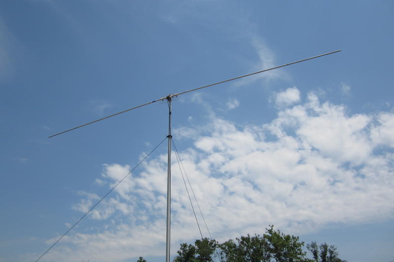
The second procedure is to make an inverted V dipole, where the antenna is the upper guy lines from the center pole out to the spreader tips.
For the ten meter case, this is nearly identical to the ground/counterpoise discussed in the Quick Vertical section. In that case, there are no extenders, so the construction is very simple. In the 20 meter case, all the same problems are encountered as above except that the wire load is acting as the upper guy lines rather than being in the spreaders. We also suggest using light wire for the 20 meter version. In fact, # 18 or # 20 hook-up wire works well, and the insulation should be left on.
We prefer the un-tinned type that is commonly available at Radio Shack. Using, the 6′ center pole, the length to the tip should be just about correct, however, the insulation slightly reduces the velocity factor, so you can shorten the extender or use a small length of Nylon fish line to extend the wire.
Note, the 17 and 20 meter versions of these dipoles are fairly large structures and can not be built up in small spaces. They are also rather flimsy, and go through lots of distortion when being tipped up. These are better erected from a push-up mast with the rotator near the top of the mast. This Dipole antenna gives the same gain as all other dipoles, however, the Half Square is a much better DX antenna for a given elevation and may be worth the extra effort. All parts used for the construction of the dipole can be used to construct the Half Square, so there is no loss in investment if you decide to switch. Note that 6 and 10 meters require no extenders, but we do recommend that you use guys from the tips to the center post. The post should extend about 3′ above the hub.
Parts required for all 6 and 10 meters versions:
| Item | Quantity | Description |
| 1 | 1 | HUB 4-050-100, Central Quad Hub (RFJ) |
| 2 | 2 | 8′ 1/2″ OD fiberglass tubing, spreaders (MGS) |
| 3 | 1 | 8′ 1″ OD fiberglass tubing, boom (MGS) |
| 4 | 2 | GT 4-050 1/2″ Guy Ties, for tips of spreaders (RFJ) |
| 5 | 2 | GT 4-100 1″ Guy Ties, for tips of boom (RFJ) |
Extenders are required for 12 , 15, and 20 meters.
To determine how much 1/4″ fiberglass to buy, you need to calculate the approximate length required for the dipole. If the wire is to be inside the fiberglass, the velocity factor is slightly less than 90%.
The size of a typical dipole is given approximately by 468/fMHz. This formula has a small correction factor for finite wire diameter and end effects.
When the wire is inside the fiberglass tubing, the appropriate factor is about 435/fMHz, so the lengths of the spreaders require for 12, 15, 17, and 20 meters is roughly as 8.72′, 10.25′, 12.02′, and 15.33′.
Assuming 6″ overlap and 8′ lengths of 1/2″ OD spreaders, the extenders will have to be 1.22′, 2.75′, 4.52′, and 7.83′.
Obviously, there is no compelling reason to cut the 8′ of 1/4″ OD tubing for the 20 meter spreaders.
You can get both a 15 and 17 meter extender our of a single 8′ length of tubing. 15, 17 and 20 meters require lateral guys to increase the stability. This requires two 4′ lengths of 1/2″ OD tubing inserted in the two remaining sockets.
Guys should be run to the tips of both the 8′ dipole tips and the extended tips. This is also true from the central Guy post. The guys can be either 50 lb. test Nylon fishing line or Kevlar thread.
The photos associated with the Half Square antenna show structures built with both fiberglass and PVC.
Article by KQ6RH
originally available at http://www.antenna-magic.com/antenna/dipole.htm